Amplifier for computer microphone with phantom power. Microphone amplifiers: circuit
Microphone preamp, also known as a pre-amplifier or amplifier for a microphone, is a type of amplifier whose purpose is to amplify a weak signal to a linear level (about 0.5-1.5 volts), that is, to an acceptable value at which conventional audio power amplifiers operate .
The input source of acoustic signals for a preamplifier is usually vinyl record pickups, microphones, and pickups of various musical instruments. Below are three circuits of microphone amplifiers on transistors, as well as a variant of a microphone amplifier on the 4558 chip. All of them can be easily assembled with your own hands.
Circuit of a simple microphone preamplifier using one transistor
This microphone preamplifier circuit works with both dynamic and electret microphones.
Dynamic microphones are similar in design to loudspeakers. The acoustic wave affects the membrane and the acoustic coil attached to it. When the membrane oscillates, an electric current is generated in a coil exposed to the magnetic field of a permanent magnet.
The operation of electret microphones is based on the ability of certain types of materials with increased dielectric constant (electrets) to change the surface charge under the influence of an acoustic wave. This type of microphone differs from dynamic microphones in its high input impedance.
When using an electret microphone, to bias the voltage on the microphone, it is necessary to set the resistance R1
single transistor microphone amplifier
Since this microphone amplifier circuit is for a dynamic microphone, when using an electrodynamic microphone, its resistance should be in the range from 200 to 600 Ohms. In this case, C1 must be set to 10 microfarads. If it is an electrolytic capacitor, then its positive terminal must be connected towards the transistor.
Power is supplied from the crown battery or from a stabilized power source. Although it is better to use a battery to eliminate noise. can be replaced with a domestic one. Electrolytic capacitors for a voltage of 16 volts. To prevent interference, connect the preamplifier to the signal source and to the amplifier input using a shielded wire. If further powerful sound amplification is needed, then you can assemble an amplifier on a microcircuit.
Microphone preamplifier with 2 transistors
The structure of any preamplifier greatly affects its noise characteristics. If we take into account the fact that the high-quality radio components used in the preamplifier circuit still lead to distortion (noise) to one degree or another, then it is obvious that the only way to get a more or less high-quality microphone amplifier is to reduce the number of radio components in the circuit. An example is the following two-stage preliminary circuit.

With this option, the number of decoupling capacitors is minimized, since the transistors are connected in a circuit with a common emitter. There is also a direct connection between the cascades. To stabilize the operating mode of the circuit when the external temperature and supply voltage change, a direct current feedback loop has been added to the circuit.
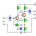
Preamplifier for electret microphone with three transistors
This is another option. The peculiarity of this microphone amplifier circuit is that power is supplied to the preamplifier circuit through the same conductor (phantom power) through which the input signal travels.

This microphone preamplifier is designed to work together with, for example, MKE-3. The supply voltage to the microphone goes through resistance R1. The audio signal from the microphone output is supplied to the VT1 base through capacitor C1. , consisting of resistances R2, R3, creates the necessary bias at the base of VT1 (approximately 0.6 V). The amplified signal from resistor R5, acting as a load, goes to the base of VT2 which is part of the emitter follower on VT2 and VT3.
Near the output connector, two additional elements are installed: load resistor R6, through which power is supplied, and separating capacitor SZ, which separates the output audio signal from the supply voltage.
Pre-microphone amplifier based on 4558 chip
The 4558 operational amplifier is manufactured by ROHM. It is characterized as a low power and low noise amplifier. This microcircuit is used in a microphone amplifier, audio amplifiers, active filters, and voltage-controlled generators. The 4558 chip has internal phase compensation, increased input voltage threshold, high gain and low noise. This op amp also has short circuit protection.

(140.5 Kb, downloads: 2,161)

microphone preamplifier for 4558
This is a good option for building a microphone preamp on a chip. The microphone preamplifier circuit is characterized by high amplification quality, simplicity and does not require much wiring. This dynamic microphone amplifier also works well with electret microphones.
With error-free assembly, the circuit does not require configuration and starts working immediately. The highest current consumption is 9 mA, and at rest the current consumption is around 3 mA.
Hello, dear readers of the site. Needed microphone amplifier for recording songs with a guitar from two microphones, so that you can adjust the voice and the guitar separately.
After searching on the Internet, I chose the domestic K157UD2 microcircuit, which was in stock. The microcircuit is a low-noise two-channel operational amplifier, which is used in a variety of stereophonic equipment. The K157UD2 operational amplifier operates over a wide range of input differential voltages and is protected against short circuits at the output.

The microphone amplifier uses a typical connection of the K157UD2 microcircuit. The numbering of pins for the implementation of the 2nd channel is indicated in brackets.

After several tests, I became convinced that there was not enough mixer to adjust the gain of both channels. I also found a transistor mixer circuit on the Internet. And when I assembled the amplifier on a breadboard, its sensitivity and quiet operation exceeded all my expectations.

And after drawing the board in LAY, the diagram of this device was born.

Both amplifier outputs are fed to the mixer input through variable resistors. The output from the mixer to the computer is mono, since it’s more convenient for me to make settings and process the recorded material. To eliminate possible interference and interference, the microphones are connected to the amplifier via a shielded wire, and the microphones themselves were purchased on the Aliexpress website. All transistors in the mixer were replaced with KT315G. The circuit is powered by a KRONA battery.

To record from a microphone, I use the free AUDACITY program, as it has a clear Russian-language interface and a large selection of tools for processing recorded material.

All parts of the microphone amplifier except the battery, variable resistors and microphones are located on two printed circuit boards (amplifier and mixer board), made of single-sided PCB 1 mm thick.


The housing for the amplifier is taken from the power supply of the scanner-printer. The amplifier can also be powered from an external voltage source; for this, it is necessary to provide a socket on the case and place it, for example, next to a toggle switch or at the end.


At the time of writing, the amplifier had worked for 5 hours in a “combat” situation and no problems with power supply had been observed yet. You can also watch a video that shows the capabilities of this microphone amplifier and explains some aspects of working with it.
An archive with printed circuit boards in lay format can be downloaded from the link.
I wish you success in repeating the design!
See you on the pages of the site!
Anatoly Tikhomirov ( picdiod), Riga
A studio or regular dynamic microphone requires a special preamplifier, since most modern audio equipment is designed to work in conjunction with electret microphones. The preamplifier in this circuit is assembled on the basis of the popular ne5532 microcircuit - a dual operational amplifier with a low noise level. In general, this preamplifier is designed specifically to amplify the signal from professional 600 Ohm microphones.
Schematic diagram of ULF
 ULF circuit on ne5532
 The amplifier consists of two gain stages: 36 dB and 16 dB. The preamp gain control is installed between these two stages and this separation helps reduce noise in the output signal.
 ULF microphone gain control
 After assembly, the preamplifier was tested with several 600 Ohm microphones together with a proprietary Marantz UMZCH. According to the results, the ULF sounds great with all microphones. To get even better results on noise and distortion, use this preamp with a 12V battery (current draw is only a couple of milliamps) and good shielded input and output wiring.
 ULF dynamic microphone homemade
 The circuit diagram and drawing of the printed circuit board for the microphone preamp are available for download to all users of the site "
A microphone amplifier is a device that increases the conductivity of a signal. This process is ensured by conductors. includes capacitors as well as thyristors. Modulators are installed in amplifiers of various types.
Tetrodes are used to increase the sensitivity of conductors. Expanders are installed in various capacities. Contactors are used to maintain stable voltage in the circuit. To find out more information about the devices, you should consider specific types of microphone amplifiers.
Single-cycle modification circuit
Single-ended microphones (shown below) are made on the basis of wire capacitors. In this case, the trigger is selected with high signal conductivity. Many models use two resistors. If we consider a low-power amplifier, then it has one filter installed.
Thyristors are used directly without a conductor. The transceivers of the models are installed behind the expanders. The output sensitivity fluctuates around 4.5 mV. In this case, the threshold voltage does not exceed 10 V. The current overload indicator depends on the conductivity of the expander.

Push-pull model
A push-pull amplifier on a microcircuit is made with field-effect capacitors. Extenders for models are used with different capacities. As a rule, the output sensitivity parameter does not exceed 5 mV. In this case, triggers are used without conductors.
On average, the threshold voltage across the insulators is 12 V. It’s easy to make this type of microphone amplifier with your own hands. For this purpose, a PP20 series microcircuit is selected. The expander itself will be required with a capacitance of around 6 pF. A thyristor is also installed with the capacitors. The conductivity of the signal in this case must be at least 2.2 microns.
Three-cycle amplifier device
Three-cycle microphone amplifiers (circuit shown below) contain field-effect capacitors. The device has two triggers in total. The output sensitivity is 5.8 mV. In this case, expanders are used at 2 pF. The contactors themselves are installed with insulators.
If necessary, you can assemble a microphone. For this, first of all, a multi-channel type microcircuit is taken. The amplifier will also require an expander with a capacitance of about 2.3 pF. If we consider a simple model, then the filter can be used of the absorbing type. The current overload parameter on average should be no more than 6 A.

How to make a common emitter model with your own hands
Microphone amplifiers (circuit shown below) with a common emitter are based on field capacitors. Resistors are used with a high conductivity parameter. First of all, a thyristor is prepared for assembly. It should be installed after the trigger. The output sensitivity of the element should be no more than 6.5 mV. In turn, the current overload parameter must be equal to 8 A. The contactor on the board is installed next to the filter.

Device with collector
Collector amps work well for studio microphones. The models use pulse-type capacitors. There are three resistors in total in the circuit. The output sensitivity parameter is on average 5.6 mV. In this case, the trigger is of a two-bit or three-bit type. If we consider the first option, then the expander is selected with a capacity of up to 5 pF.
A thyristor is used with a contactor. The transceivers themselves are located near the capacitors. The minimum output voltage is 12 V. If we consider a circuit with a three-bit trigger, then the expander is used with a capacitance of more than 5 pF. Capacitors are installed only of the vector type. In total, the model will require three modulators. The minimum output voltage is 15 V. Filters are used to stabilize the threshold current.

Devices with AGC (automatic gain control)
Amplifiers with AGC have recently become quite popular. First of all, they are characterized by low energy consumption. Tetrodes in models are used for two contacts. If we consider the circuit of a simple amplifier, the filter is installed behind the thyristor. The expander capacitance must be at least 8 pF. The output sensitivity is about 4.5 mV. In this case, open-type capacitors are allowed to be installed on a microphone amplifier with AGC. In total, the model will require three scalar transistors. The model's expanders are installed in sequential order.
Canyon Studio Microphone Models
For studio models, microphone amplifiers (the diagram is shown below) are made on the basis of a pulse modulator. A total of two transceivers are required for assembly. Capacitors are used with output contactors. The minimum output sensitivity is 2 mV. In this case, the trigger can be used without insulators. The filter is installed as an absorption type. On average, the threshold voltage in amplifiers of this type is 12 V.

Models for Defender condenser microphones
The amplifier on the microcircuit consists of field resistors. Beam tetrodes are used to solve signal conduction problems. In this case, triggers are used of both pulse and operational types. Modulators are installed with low conductivity. The output sensitivity parameter is no more than 5 mV. In this case, expanders can be used with a capacitance of up to 4.2 pF. Models with chromatic expanders are rare.
Amplifier for electret microphone "Sven"
Microphone amplifier for folding based on pass-through capacitors. The standard device circuit has three resistors. They are installed in sequential order. Their signal conductivity is about 8 microns. In this case, the output sensitivity parameter fluctuates around 3.3 mV. Thyristors for a microphone amplifier for an electret microphone are selected without contactors. Triggers are most often used of the low-frequency type. There is a tetrode next to the filter. The expander is suitable for models with a small capacity. Modulators are most often installed behind the trigger.
Model for Esperanza microphones
Amplifiers for these microphones are made of a single-acting type. The models use field capacitors. Resistors are most often installed with contactors. There are three expanders in total in the circuit. Their capacitance indicator is 4.5 pF. In this case, the output sensitivity does not exceed 8 mV. Triggers for devices are selected for three contacts.
The minimum threshold voltage parameter is 12 V. Filters for devices are only suitable for the absorbing type. They must be installed next to the modulator. Direct contactors in devices are used with low signal conductivity. Due to this, it is possible to solve the problem with negative polarity.
Device for Trust microphones
The microphone amplifier on a microcircuit for this model is based on pass-through capacitors. In total, the device will require two resistors. They must be installed together with filters. To assemble the amplifier yourself, you will need an expander. Many experts believe that the maximum resistance in the circuit should be 50 ohms.
In this case, the trigger does not overheat too much. Contactors for the model are open type. In some cases, amplifiers contain two-bit triggers. Such devices are classified as push-pull type. In this case, modulators are installed without insulators. The transceiver can be used with a regulator. Filters are installed as standard of the absorption type. On average, the output sensitivity parameter in the circuit is 3.5 mV.

Plantronics Microphone Amplifier
A simple microphone amplifier for this model contains field-effect resistors. There are a total of two pairs of capacitors in the circuit. They are installed with an expander. The transceiver can be used of a dipole or pulse type. If we consider the first option, then the expander capacitance should not exceed 5 pF. In this case, the trigger is used with a contactor. Amplifier insulators are installed behind the capacitors.
If we consider the modification with a pulse element, then the trigger is of a three-digit type. In this case, filters are used with a mesh lining. All this is necessary in order to solve problems with negative polarity. The thyristor is installed directly behind the modulator. The expander capacitance must be at least 5 pF.
This article describes how, using an operational amplifier, you can independently make a simple signal amplifier for an electret microphone and connect it to a computer. Why is this necessary? Well, this is a very useful thing. Using such a device, you can, for example, make a directional microphone and talk to a friend who is at a considerable distance from you, or you can even talk to the same friend directly through the wall.
Let me make a reservation right away, the situation when you simply listen to what your friend is chatting about, being a hundred meters away from you, or eavesdrop on him through the same wall, threatens not only with complicating your relationship with your friend, but also with troubles with the law, since such It is strictly forbidden to do things in our country (unless, of course, you have a court sanction to do so). In short, I warned you.
So, actually, let's return to the amplifier. The scheme presented here is the best one and is calculated according to the best one. There is only one small nuance.
Since we use unipolar power supply, naturally we cannot amplify negative signals. To solve this problem, the zero level has been artificially shifted up by half the supply voltage and we consider the input signal relative to this new zero level. How did we do it? Yes, very simple. They took it and applied a signal from a divider, which divides the supply voltage in half, to the non-inverting input. Subsequently, after amplifying the useful signal, the DC component is removed by capacitor C5.
The gain of the circuit is determined by the formula: K=R4/R3. To be able to smoothly adjust the gain of the circuit, you need to use a tuning resistor as resistor R4.
This device is connected to the Line-in connector of the computer sound card.
Schematic elements:
R1, R2 are 47 kOhm resistors. In principle, any will work, as long as the current through the divider is 100..200 times greater than the input current of the op-amp. Well, naturally, too much divider current reduces the battery life.
R3 is a 1 kOhm resistor. Also, in general, any, as long as you get the required gain.
R4 is a 100 kOhm trim resistor.
R5, R6 are resistors, 4.3 and 47 kOhm, respectively.
C1, C2 - op-amp power supply filters, 0.1 µF ceramics and 100 µF / 6.3 V electrolyte, respectively.
C3, C5 - isolation capacitors, 10 µF ceramics (full on boards of old hard drives)
C4 - ceramic capacitor 4.7 nF (any from 1 to 10 nF will do)

Mic - any electret microphone (you can take it from an old cell phone, tear it out of cheap headphones with a microphone, or just buy it at any electronics store). Chinese tablets, such as those in the photo, cost only 10 rubles in the store.
Op-amp - in principle, any operational amplifier capable of operating from a 3-volt single-polar supply should be suitable. I used LM358.
Up is a 3V lithium tablet (the same as on the motherboard; the battery holder, by the way, can be removed from there).
With these elements, the device consumes a tiny current - less than 1 mA.
That, in general, is the entire amplifier. This is where we finish the electrical part and move on to the acoustic part. The amplifier that we have made will simply amplify the signal from the microphone, no matter from which direction this signal comes to the microphone. How can we make our microphone directional? The simplest thing you can do is attach a horn to it. You can use anything as a mouthpiece: a plastic cup, a glass jar with a hole, a wooden box without one wall, even just a bag rolled up from paper. To more reliably shield sounds from directions you don’t need, you can wrap a scarf around the horn.
Example of a finished device:


How to work with this device? The operating algorithm is as follows: turn the knob of resistor R4 to minimum, insert the battery, connect it to the computer (Line-in input), point it to the place where you want to hear the sound (or lean your horn against the wall) and begin to smoothly turn the knob of resistor R4 ( increase its resistance) until sound appears.
The computer mixer must be configured so that the audio from the Line-in input goes to the speakers and/or to the recording program (if you want to record).
If you accidentally overdo it with the gain, you will immediately hear it through the characteristic sharp ringing from the speakers (in this case, the gain needs to be reduced a little).
Download the amplifier board (DipTrace 2.0, wiring for SMD components)
 Microphone amplifiers: circuit
 Song about the petrel, poem by Maxim Gorky
 Distributing power between speakers Connecting two speakers to one channel