We study the terms of testing electrical protective equipment. Voltage indicators
In the process of working at electrical installations, the use of protective equipment (AP) is required - items that prevent a person from falling under the negative effect of electricity. It is important to understand correctly which APs should be used, what they are for, and how to maintain them in good condition, where special attention should be paid to checking and replacing.
Protective equipment against electric current
APs protect workers from the following electricity-related factors:
- electric shock - means of electrical protection;
- the negative impact of exposure to a powerful electromagnetic field - protective equipment in electrical installations, where the voltage reaches 330 kV or more;
- the need for personal protective equipment - PPE.
As can be seen from the table, funds are basic (OZS) and additional (DZS).
List of basic and additional means of electrical protection
| Main insulating electrical protective facilities | Additional insulating electrical protective facilities |
||
|---|---|---|---|
| above 1000 V: | In electrical installations with voltage up to 1000V: | In electrical installations with voltage above 1000 V: | In electrous- tanovkah nap- disguise up to 1000V: |
| voltage indicators | voltage indicators | insulating caps and linings | insulating caps, coatings and overlays |
| insulating pliers | insulating pliers | dielectric carpets and insulating pads | dielectric carpets and insulating coasters |
| insulating rods all kinds | insulating rods all kinds | dielectric gloves and boots | dielectric galoshes |
| devices and devices for ensuring the safety of work during measurements and tests in electrical installations (voltage indicators for checking the coincidence of phases, electrical pliers, cable piercing devices, etc.) | electrical pliers, dielectric gloves, manual insulating tool | transfer and potential equalization rods | stairs attached, ladders insulating fiberglass teak |
| special protective equipment, insulating devices and fixtures for work under voltage in electrical installations with a voltage of 110 kV and above (except for rods for transferring and equalizing potential) | dielectric gloves | ladders, insulating fiberglass ladders | |
Means of protection against electric current
OZS is needed in the process of servicing electrical installations to create a reliable barrier when touching current-carrying elements under voltage. A distinctive feature of DZS is that they do not protect against electric shock on their own, but must be used in conjunction with OZS, the reliability of which they increase by protecting against arcing, step voltage or electric shock from conductive elements. In the figure above, in the table, OZS and DZS are in separate lists.
Special requirements are imposed on the properties of materials used for the manufacture of OZS. They have a stable dielectric characteristic. They include porcelain, bakelite, getinaks, rubber, ebonite, etc.
The quality of dielectric gloves and other products depends on which rubber is used. It is subject to the requirements of high electrical resistance and sufficient elasticity. All products have a certain service life, because over time, the quality of rubber deteriorates under the influence of the external environment, petroleum products, aggressive substances and from damage. Therefore, tests are carried out for the AP, and a certain frequency is observed here, in accordance with the established standards.
Products are manufactured for two different applications in electrical installations:
- Up to 1000 V - OZS. Not applicable for higher voltage.
- Over 1000 V - used as a DZS together with the main OZZ or when controlling switches for voltages over 1000 V. These dielectric gloves are allowed to be used as OZZ in electrical installations less than 1000 V.
Gloves are worn completely so that the bells can be closed on top of the sleeves of clothing. To do this, their width should be sufficient. Wrapping their edges is not allowed.
Gloves are made with or without a seam, from special rubber (fig. below). The fact that they are AP is indicated by the marking Ev or En. The sizes used should be sufficient to be able to put on knitted prints from below.

Dielectric gloves: a - seamless; b - single-seam
Checking products before work includes an external inspection for defects, cuts, tears, dirt and excessive moisture. All these factors significantly reduce the dielectric properties of the ZS. Gloves are checked for tightness by folding in the direction from the bell to the fingers.
To protect the used dielectric gloves from external influences, ordinary work gloves are put on from above.
During operation, gloves are periodically washed with soda, soap and other detergents, after which they must be dried.
Electronic glove test
Products are tested in the aquatic environment (fig. below). To do this, water is poured into them with an indentation from above of about 50 mm, and then immersed in a bath so that the edges remain dry. A voltage is applied to the metal surface of the bath (8) and to an electrode placed in a glove and the current value is controlled. If several products are tested, the current in each of them is controlled by switching the milliammeter.
In the event of a breakdown or when the current through the glove is above the norm, it is rejected.
Power is supplied through a high voltage transformer (1). Before it, you can additionally connect an autotransformer to control the magnitude of the test voltage.

Scheme of the device for testing dielectric gloves: 1 - high-voltage transformer; 2 – switch contacts; 3 - shunt; 4, 7 – arresters; 5 - inductive load; 6 - current device; 8 - capacity
Indications in each product are determined by a milliammeter (6) connected by contacts (2). At the same time, arresters (4) are designed to protect switched circuits. If the tested glove is pierced, the choke (5) limits the current and protects the circuit with the measuring device from overload.
The table below shows the established standards for the frequency of testing dielectric gloves and other OZZ.
Table of test parameters for AP in electrical installations
| Name for- protective means | Voltage electrostatic novki, kV | Test voltage, K | duration, min. | Periodicity tests |
|---|---|---|---|---|
| Operational insulating bars | 10 | 40 | 5 | 1 time per 2 years |
| Voltage indicators above 1000 V | Up to 10, over 10, up to 20 | 40 60 | 5 5 | 1 time per year |
| Voltage indicators up to 1000 V | up to 0.5 | 1 | 1 | _-_ |
| Voltage indicators for phasing | to 10 | 40 | 5 | |
| Cable puncture device | to 10 | 40 | 5 | _-_ |
| Insulating pads - hard | up to 0.5 up to 10 | 1 20 | 5 5 | 1 time per 2 years |
| - flexible | up to 0.5 | 1 | 1 | >> |
| Insulating caps on the cores off. cable | to 10 | 20 | 1 | 1 time per year |
| Flexible insulating strips for live work | up to 1 | 6 | 1 | |
| all voltages | 6 | 1 | 1 time in 6 months. |
Insulating rods
The device consists of three parts: insulating, working and handle. The device is used on elements with a passing current, or near them. Working elements can be clamps, tips, and other designs, depending on the purpose. The universal head is made removable to perform various operations. It securely fixes interchangeable fixtures. The bar becomes a control device after fixing a voltage indicator on it. The number of links used on the insulating part may vary. Telescopic devices are convenient, but one-piece structures are also used. The norms of the weight load on the arm are normalized and selected so that one or two people can work.
With the use of rods, insulation quality checks are made, fuses are replaced, various parts are installed, operations are performed with disconnectors, electrical parameters are measured, grounding is applied, etc.
With the help of a bar, you can free a person who has been affected by an electric current.
Devices of various types of rods and requirements for them are standardized.
On fig. a bar with a clamp is shown and all components of the device are marked.

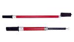
Rods used in electrical installations: a - operational; b - portable grounding
Portable grounds contain clamps for connection to current-carrying parts or wires (fig. b). They may be removable or non-removable.
Rods are tested under high voltage applied to their insulating parts. The parameters are presented in the table above. Voltage is applied between the working part and the removable electrode, which is temporarily attached near the stop between the handle and the insulating part (Fig. a).

Boom Performance Test Diagram
The voltage value is regulated by an autotransformer installed at the input of the device (voltage regulator). The passing current is checked by a milliammeter protected from overload using a spark gap (P) (Fig. b).
Insulating pliers
With the help of insulating pliers, they replace fuses, remove linings, fences, and perform other similar work. They are made entirely of non-conductive material (up to 1000 V) or with metal jaws. Their mass allows one electrician to work.
Electrical strength tests are carried out similarly to rods. The parameters are presented in the table above.
Instead of insulating pliers, a rod can be used if a suitable work item is selected.
Electrical tongs are used to measure parameters in circuits up to 1 kV. They contain a secondary winding connected to the instrument. The high-voltage bus or wire serves as the primary. The working part is a detachable magnetic circuit with a winding and a device.
Voltage indicators
The devices are used to check the voltage in electrical installations, as well as the phasing of high-voltage equipment. Technical requirements for them are set out in GOSTs. As indicators, gas-discharge or LED lamps are used, ignited by a capacitive current passing through them. Pointers can be non-contact or with an electrode for direct contact with the bus or wire. Indication can be light, sound or combined. In this case, the signals must be clear and recognizable.
Figure (a) below shows the assembled high voltage indicator UVNU-10. To create a working state, it is necessary to unscrew the thread, turn the working part 180 0 and screw it in again (Fig. b).

Voltage indicator UVNU-10
Tests are carried out for an isolated area and the indication voltage is checked. The frequency is regulated by the established standards (1 time per year). The insulated part is checked in the same way as the rods.
The lamp lights up when the voltage reaches 25% of the nominal.
To test the LED lamp, voltage is applied only to the working part.
Before operation, the UVN is checked by touching the current-carrying parts with the working element for 5 seconds. For U>1000 V), dielectric gloves are required for the device.
Portable grounding
Devices are needed to protect people working on live parts of electrical installations after they have been disconnected from voltage induced or applied by mistake. Designs can be rod or rodless.
Test methods do not differ from insulating rods.
If there is no grounding rod, the insulating flexible grounding element is checked in parts. You can test it in one go by winding it into a bay.
Dielectric galoshes and boots
Dielectric footwear is an additional means of protection for OZS, as well as protection against step voltage in electrical installations or on overhead power lines.
Galoshes and boots should be worn on top of regular shoes. Outwardly, they differ from it in a not very spectacular appearance, but the main thing here is safety.

Dielectric footwear for work on electrical installations
Before using the products, it is necessary to examine them for defects: hard inclusions, delaminations, breaks, etc.
Electrical testing of shoes is carried out according to the same technology as with dielectric gloves. The norms for filling with water galoshes and bots are respectively 2 cm and 5 cm from the top edge.
Hand tool
As an OZS at electrical installations up to 1 kV, a manual insulating tool (RII) is used. It is made in two types:
- metal with full or partial electrical insulation coating (fig. below);
- entirely of electrically insulating material or with metal inserts.

Insulated coated hand tools
The insulating coating of the metal must be strong enough, resistant to moisture and oil products. The handles of pliers, wire cutters, etc. are equipped with stops that prevent the hand from touching metal parts during operation.
The tool must be inspected before each use. The protective layer must be free of defects that reduce its strength and insulating properties.
Every six months, the hand tool is inspected by a designated worker who records the examination data.
The tool is tested at a voltage of 2 kV with a time delay of 1 min, and the frequency should not be less than once a year.
Rules for the use of SZ
- Personnel in electrical installations who are provided with the required protective equipment must be appropriately trained and able to handle them to ensure safety.
- APs are marked with the designation of the manufacturer, type of product, production date, and a stamp on electrical tests is required.
- Objects and brigades on departure are completed with inventory AP, as required by the norms and operating conditions. APs are also issued to employees individually. Their distribution is recorded in the lists, which are approved by the head of the electrical facilities. They indicate the storage locations of the AP.
- Unsuitable protective equipment or past service life are subject to withdrawal with a note in the accounting journal. The entry must conform to a certain form.
- APs must be properly operated by workers. They are required to monitor the serviceability of inventory and control the timing of verification.
Expired APs are strictly prohibited! AP may only be used for the purposes specified in the instructions. It is especially necessary to monitor the correspondence between the voltages of means and electrical installations.
- OZS can only be used outdoors in dry weather. At high humidity, only special APs can be used.
- Where there is a limit ring, it is allowed to hold the AP during operation only by the handle, up to the limiter.
Checking the status of the AP
- All operated APs, with the exception of some DZS, are numbered, which is done by paint, embossing on parts or by attaching tags.
- There is a frequency of inspection (once every six months, and grounding rods - once every three months) of the state of the AP by the appointed contractor, who must record the data of the verification inspection in writing.
- Received into operation, new APs are tested (if the standards are established for this) and stamps are placed on the products that establish the terms of use for the prescribed period. If the result is negative, the stamp is crossed out with paint.
- The results of the checks are recorded in the logs, and separate protocols are drawn up at the third-party APs.
It is possible to store and move the AP only under the conditions of their reliable protection from damage, dirt and moisture. It is forbidden to store them together with tools. It is also not allowed to hit the AP with various aggressive substances and oil products.
When transported by mobile teams, protective equipment is in covers, boxes or bags.
AP test rules
- The frequency of testing of the AP is always maintained, but additional extraordinary tests are carried out (after repair, when replacing faulty parts, after an impact or fall, if a malfunction is suspected).
- Checking protective equipment can only be carried out if there is no damage, the insulation is in a normal state, if there is a factory marking, number, and completeness. The surface of the insulation must be free from visible defects. Structurally, the devices are made so that they can be easily cleaned or prevent dust and moisture from entering inside. The remarks must be eliminated, otherwise the AP will not be allowed to test for dielectric strength.
- When checking the insulation, the voltage can be raised to 1/3 of the nominal voltage quickly, then smoothly. After reaching the norm and holding the time interval, the voltage decreases by 1/3 of the test voltage or completely, and then turns off. There are standards for the current passing through the insulation for each material.
- The breakdown is determined visually or according to the instruments. Then the product is rejected.
- ZS after shutdown of the installation are checked for the absence of overheating.
Video about SZ
About personnel protection equipment and their standardization is described in this video.
For the safety of workers at electrical installations, APs are used; over time, they lose their properties. Therefore, there is a predetermined frequency of regular and extraordinary inspections of the AP, so that if their performance deteriorates, they can be removed in time and replaced with new ones. When the correct organization of the use and verification of protective equipment is carried out, they provide the necessary electrical safety of work.
To check the presence or absence of voltage in electrical installations up to 1000 V, two types of indicators are used:
bipolar - working with the flow of active current;
single-pole - operating with capacitive current.
Two-pole pointers are designed for electrical installations of alternating and direct current, and single-pole - for electrical installations of alternating current.
Two-pole pointers consist of two housings containing elements of the electrical circuit. The elements of the electrical circuit are interconnected by a flexible wire that does not lose elasticity at low temperatures, at least 1 m long.
The electrical circuit of a two-pole pointer with visual indication may contain a pointer-type device or a digital sign-synthesizing system (with a small-sized power supply for the indicating scale). Pointers of this type can be used for voltages from 0 to 1000 V.
The electrical circuit of a single-pole voltage indicator must contain an indication element with an additional resistor, a tip contact and a contact on the end (side) part of the housing, with which the operator's hand comes into contact.
The length of the uninsulated part of the contacts - tips should not exceed 5 mm. Tip contacts must be rigidly fixed and must not move along the axis.
Operational tests of voltage indicators up to 1000 V consist in determining the indication voltage, checking the circuit with increased voltage, measuring the current flowing through the indicator at the highest operating voltage, and testing insulation with increased voltage.
To check the indication voltage for a two-pole pointer, the voltage from the test setup is applied to the contacts - tips, for a single-pole pointer - to the contact - tip and the contact on the end (side) part of the housing.
The indication voltage of voltage indicators up to 1000 V should not exceed 50 V.
To check the circuit for a two-pole pointer, the voltage from the test setup is applied to the contacts - tips, for a single-pole pointer - to the contact - tip and the contact on the end (side) part in accordance with the diagrams in Fig. 5.
The test voltage when checking the circuit must exceed the highest value of the operating voltage by at least 10%. The duration of the test is 1 minute.
The value of the current flowing through the pointer at the highest value of the operating voltage must not exceed:
0.6 mA for a single-pole voltage indicator;
10 mA for a two-pole voltage indicator with elements providing visual or visual-acoustic signal indication;
for voltage indicators with an incandescent lamp up to 10 W with a voltage of 220 V, the current value is determined by the power of the lamp.
The current value is measured using an ammeter connected in series with the pointer in accordance with the diagram in fig. 6.
To test the insulation of voltage indicators with increased voltage, for two-pole indicators, both insulating cases are wrapped in foil, and the connecting wire is lowered into a grounded vessel so that water closes the wire, not reaching the handle by 9 - 10 mm. One wire from the test setup is connected to the contacts - tips, the second, grounded, to the foil and lowered into the water in accordance with Fig. 7.
For single-pole voltage indicators, the insulating housing is wrapped with foil along the entire length up to the limit stop. A gap of at least 10 mm is left between the foil and the contact on the end of the housing. One wire from the test setup is connected to the contact - the tip, the second, grounded - to the foil.
The insulation of voltage indicators up to 500 V must withstand a voltage of 1 kV, and voltage indicators above 500 V - 2 kV. The duration of the test is 1 minute.
Rice. 5 Schemes for testing a single-pole voltage indicator up to 1 kV. 
Rice. 6 Test schemes for a two-pole voltage indicator up to 1 kV.

Rice. 7 Schemes for testing the insulation of a two-pole voltage indicator up to 1 kV.
Voltage indicators for phase matching
Pointers are designed to check the phase coincidence on overhead and cable lines, transformers and other electrical installations from 3 to 110 kV.
Pointers are two-pole devices of the light-signal type, operating in direct contact with live parts of electrical installations under voltage.
Pointers consist of two tubular cases made of electrically insulating material containing working, insulating parts and handles. Elements of the electrical circuit (contact electrodes, gas-discharge indicator lamp and corresponding electronic components) are mounted in the working parts of the pointer itself and the tube with additional resistance, connected by a flexible wire with reinforced insulation. The tube with additional resistance is arranged in the same way as a conventional voltage indicator, but instead of a capacitor and a gas-discharge lamp, heat-resistant resistances are inserted inside.
The design of the working parts of the indicators should exclude the possibility of breakdown and flashover with simultaneous contact with current-carrying and grounded parts of electrical installations.
During operational tests, the indicators are checked according to the schemes of consonant and counter switching, the electrical strength of the working and insulating parts and the connecting wire is checked.
When checking the indicator according to the consonant switching circuit, both contact electrodes are connected to the high-voltage output of the transformer according to the circuit in fig. 8.
When checking the indicator according to the counter-connection scheme, one of the contact electrodes is connected to the high-voltage output of the transformer, and the second to the grounded output of the transformer according to the diagram in Fig. nine.
During the test, the indicator voltage is fixed, the values of which, depending on the circuit, are given in Table 3.
When checking the electrical strength of the longitudinal insulation of the working parts, the test voltage is applied to the contact electrode and the threaded connector element for 1 minute. Tests are made according to the scheme of fig. 2.
In this case, the test voltages must have the following values:
12 kV - for an indicator with voltage up to 10 kV;
70 kV - for an indicator with a voltage of 35 kV;
100 kV - for an indicator with a voltage of 110 kV.
When checking the electrical strength of the longitudinal insulation of the insulating parts, the test voltage is applied for 5 minutes to the metal connector and the wire bandage applied at the restrictive ring. Tests are made according to the scheme of fig. 3.
In this case, the test voltages must have the following values:
40 kV - for an indicator with voltage up to 10 kV;
105 kV - for an indicator with a voltage of 35 kV;
190 kV - for an indicator with a voltage of 110 kV.
A flexible wire is tested with a voltage of 20 kV for 1 minute for indicators up to 20 kV, for indicators of 35-110 kV - 50 kV for 1 minute.
The wire is lowered into a bath of water so that the distance between the wire termination point and the water level is within 60-70 mm for indicators up to 20 kV and 160-180 mm for indicators up to 35-110 kV. Voltage is applied to a contact electrode immersed in water.
In operation, mechanical tests of pointers are not carried out.

Rice. 8 Scheme of consonant inclusion of the voltage indicator. 
Rice. 9 Scheme of counter switching on the voltage indicator. 
Rice. 10 Scheme of testing the connecting wire of the voltage indicator.
Cable puncture devices
Cable piercing devices are designed to indicate the absence of voltage on the repaired cable up to 10 kV before cutting it by piercing the cable along the diameter and shorting all the conductors of different phases to each other and to the ground.
The devices include a working body, a grounding device, an insulating rod and a drive.
The grounding device includes a grounding rod with a grounding conductor and clamps.
The length of the insulating part of the device must be at least 230 mm.
The cross section of the ground contact must be at least 25 mm².
During operational tests, the operability of the device is checked by puncturing a sample of the ABASHV 3 x 240 type cable, and in mechanical type puncture devices, in addition, the force applied to the drive belt is measured.
During operational tests, the insulating parts of the devices (insulating rod or insulating insert of the electric drive) are tested with an increased voltage of 40 kV for 5 minutes.
The test voltage is applied to the insulating part of the rod or to the metal flange of the electric drive and a special terminal.
Dielectric rubber gloves
Gloves are designed to protect hands from electric shock when working in electrical installations up to 1000 V as the main electrical protective equipment, and in electrical installations above 1000 V - as an additional one.
In electrical installations, it is allowed to use only gloves marked with protective properties EN (for protection against electric current with voltage up to 1000 V), EV (for protection against electric current with voltage above 1000 V).
The length of the gloves must be at least 350 mm.
In operation, only electrical testing of gloves is carried out.
Once every 6 months, gloves must be tested with an increased voltage of 6 kV for 1 minute, the current through the glove should not exceed 6 mA.
When testing, dielectric gloves are immersed in a metal vessel with water at a temperature of 25 + 10 ° C, which is also poured into these products. The water level both outside and inside the products must be 50 mm below the top edge of the gloves.
The protruding edges of the gloves must be dry. One terminal of the test transformer is connected to the vessel, the other is grounded. An electrode connected to ground through a milliammeter is lowered inside the gloves. The product is rejected if the current passing through it exceeds the norm or sharp fluctuations of the milliammeter needle occur.
In the event of a breakdown, the defective product or the entire installation is turned off.

Fig.11. Schematic diagram of testing dielectric gloves, overshoes and galoshes.
Boots, rubber dielectric galoshes
Special dielectric footwear (glued overshoes, rubber glued or shaped boots in tropical design) is an additional electrical protective equipment when working in closed, and in the absence of precipitation - in open electrical installations. In addition, dielectric boots and galoshes protect workers from step voltage.
Shoes are used:
galoshes - at voltages up to 1000 V;
boots - at all voltages.
According to the protective properties of shoes denote:
En - rubber glued galoshes;
Ev - rubber glued and molded boots.
The height of the bot must be at least 160 mm.
In operation, dielectric galoshes are tested with a voltage of 3.5 kV, and boots with a voltage of 15 kV for 1 minute. The currents flowing through the products should be no more than 2 mA for galoshes and 7.5 mA for boots.
When testing, the water level both outside and inside horizontally installed products should be 20 mm below the sides of the galoshes and 50 mm below the edge of the lowered lapels of the boots.
Tests are carried out according to the scheme of Fig. eleven.
At the end of the tests, the products are dried.
Dielectric rubber carpets and insulating pads
Dielectric rubber carpets and insulating stands are used as additional electrical protective equipment in electrical installations up to and above 1000V.
Carpets are used in closed electrical installations of all voltages, except for particularly damp rooms, and in open electrical installations in dry weather.
Stands are used in damp and polluted rooms.
Carpets are manufactured in accordance with the requirements of GOST 4997-75, depending on the purpose and operating conditions of the following two groups:
1st group - normal execution;
2nd group - oil and petrol resistant.
Carpets (recommended to use at least 50 x 100 cm) are made in the following sizes:
length from 500 to 1000 mm;
over 1000 to 8000 mm;
width from 500 to 1200 mm;
6 + 1 mm thick.
Carpets must have a corrugated front surface and be of one color.
The insulating support consists of a flooring fixed on support insulators with a height of at least 70 mm. It is recommended to use insulators of the CH-6 type, produced specifically for the manufacture of stands.
Flooring with a size of at least 500 x 500 mm should be made of wooden planks without knots and slant, planed from well-dried wood. The gaps between the bars should not exceed 30 mm. Solid decks are not recommended, as they make it difficult to check that there is no accidental shunting of the insulators. The flooring must be painted on all sides.
Insulating supports must be strong and stable. In the case of using removable insulators, their connection to the flooring must exclude the possibility of slipping of the flooring. To eliminate the possibility of overturning of the insulating support, the edges of the flooring should not protrude beyond the supporting surface of the insulators.
In operation, carpets and coasters are not tested. They are rejected during inspections. Carpets should be cleaned of dirt and inspected at least once every 6 months. If defects are found in the form of punctures, tears, cracks, etc. they should be replaced with new ones.
The supports are inspected once every 3 years for the absence of violations of the integrity of the support insulators, kinks, weakening of the connection between the individual parts of the flooring. If these defects are found, they are rejected, and after the defects are eliminated, they are tested according to the standards of acceptance tests.
Used during the operation and repair of electrical installations.
Today's article will focus on low voltage indicators.
Low voltage indicators (UNN) are used to check the presence or absence of voltage in electrical installations up to 1000 (V) on those live parts where work will be performed. Also, UNN is used to check the coincidence of phases, i.e. phasing low voltage.
Low voltage indicators, or in another way they are also called voltage indicators up to 1000 (V), are of 2 types:
- single-pole
- bipolar
Therefore, the application will depend on which pointer you use.
There are a large number of varieties of low voltage indicators from various manufacturers.
I will not dwell on each type, but will only talk about the most common and reliable low voltage indicators that I personally use.
For example, a single-pole low voltage indicator in the form of an indicator screwdriver is used in electrical installations only with alternating current with a voltage of 100 (V) to 500 (V) and a frequency of 50 (Hz). The principle of operation of such a pointer is based on the flow of capacitive current.
The two-pole low voltage indicator (UNN-10K) has a wider application. It can be used in electrical installations, both AC voltage from 110 (V) to 500 (V) and frequency 50 (Hz), and DC voltage from 110 (V) to 500 (V).

Its principle of operation is based on the glow of a gas-discharge lamp when an active current flows through it.
I use a two-pole low voltage indicator (PIN-90M) just as often. Its principle of operation and design is similar to UNN-10K.

The difference lies only in the limits of the controlled voltage. Its operating voltage ranges from 50 (V) to 1000 (V).
- insulation testing of handles and wires
- high voltage test
- indication voltage detection
- measurement of the current passing through the UNN at the highest operating voltage
1. Testing the insulation of handles and wires of low voltage indicators
The insulation test of the housing handles and wires of low voltage indicators is carried out once a year according to the following schematic diagram:

Both cases (handles) of a two-pole low voltage indicator are wrapped in foil. The connecting wire is lowered into a bath of water, where the water temperature should be within 10 - 40 ° C. It is necessary to maintain a distance of 0.8 - 1.2 (cm) between the water and the indicator housings.
We connect the first output from the test transformer to the tip electrodes. The second (grounded) terminal must be lowered into a bath of water and connected to the foil.
Similarly, the insulation of the housing (handle) is also tested for single-pole low voltage indicators. The body is wrapped in foil along the entire length. It is necessary to maintain a distance of 1 (cm) between the foil and the electrode located on the end of the pointer. One lead from the test device is connected to the tip electrode. The other (grounded) lead is to the foil.
For UNN with an operating voltage of up to 500 (V), a test voltage of 1000 (V) is applied for 1 minute.
For UNN with operating voltage up to 1000 (V), test voltage 2000 (V) is applied for 1 minute.
2. Testing low voltage indicators with increased voltage
The test of low voltage indicators with increased voltage is carried out as follows.
A test voltage of 1.1 of the highest operating voltage of the UNN is applied between the tip electrodes of bipolar indicators, or between the tip electrode and the end part of single-pole indicators for 1 minute.
3. Determining the indication voltage
The voltage from the test device is smoothly increased, while fixing the voltage indication of the voltage indicator (UNN).
Low voltage indicators must have an indication voltage of not more than 50 (V).
4. Measurement of the current passing through the UNN at the highest operating voltage
The voltage from the test device is smoothly increased to the highest operating voltage of 1000 (V), while fixing the amount of current flowing through the UNN.
For two-pole voltage indicators, the current value should not exceed 10 (mA).
For single-pole voltage indicators, the current value should not exceed 0.6 (mA).
How to use the voltage indicator?
Before applying and using a low voltage indicator, you must make sure that it is in good condition by touching the current-carrying parts of the electrical installation that are obviously energized. It is also necessary to check the presence of a stamp on the testing of UNN.
Checking the absence of voltage with a low voltage indicator is carried out on live parts by direct contact. The contact time must be at least 5 seconds.


When using a single-pole low voltage indicator, the use is not allowed, because. it is necessary to ensure contact between the electrode on the end of the housing and the human finger.


P.S. This concludes the article on the topic of the low voltage indicator. If you have any questions while studying the material of the article, then please ask them in the comments. Don't forget to subscribe to new articles from the site. The news about the release of a new article will come to you directly to your mailbox.
Voltage meters are portable devices designed to check the presence or absence of voltage on live parts. Such a check is necessary, for example, when working directly on disconnected current-carrying parts, when monitoring the serviceability of electrical installations, finding damage in an electrical installation, checking an electrical circuit, etc.
In all these cases, it is required to establish only the presence or absence of voltage, but not its value, which, as a rule, is known.
All indicators have a light signal, the ignition of which indicates the presence of voltage on the part being checked or between the parts being checked. Pointers are for electrical installations up to 1000 V and above.
Pointers designed for electrical installations up to 1000 V are divided into two-pole and single-pole.
Two-pole indicators require touching two parts of the electrical installation, between which it is necessary to determine the presence or absence of voltage. The principle of their operation is the glow of a neon light bulb or incandescent lamp (with a power of not more than 10 W) when a current flows through it, due to the potential difference between the two parts of the electrical installation that the pointer touches. Consuming low current - from fractions to a few milliamps, the lamp provides a stable and clear light signal, emitting orange-red light.
After the discharge occurs, the current in the lamp circuit gradually increases, i.e. the resistance of the lamp, as it were, decreases, which eventually leads to the failure of the lamp. To limit the current to a normal value, a resistor is connected in series with the lamp.

Two-pole indicators can be used in both AC and DC installations. However, with alternating current, the metal parts of the pointer - the lamp base, wire, probe can create a capacitance relative to the ground or other phases of the electrical installation, sufficient so that when only one probe touches the phase, the pointer with a neon bulb glows. To eliminate this phenomenon, the circuit is supplemented with a shunt resistor that shunts a neon light bulb and has a resistance equal to the additional resistor.
 Single-pole pointers require touching only one - the current-carrying part under test. Communication with the ground is provided through the body of a person who makes contact with the pointer circuit with a finger. In this case, the current does not exceed 0.3 mA.
Single-pole pointers are usually made in the form of an automatic pen, in the body of which, made of insulating material and having a viewing hole, a signal light and a resistor are placed; a metal probe is fixed on the lower end of the housing, and a flat metal contact on the upper end, which the operator touches with his finger.
A single-pole pointer can only be used in alternating current installations, since with direct current its light does not light up even in the presence of voltage. It is recommended to use it when checking secondary switching circuits, determining the phase wire in electric meters, lamp sockets, switches, fuses, etc.
When using voltage indicators up to 1000 V, you can do without protective equipment.
Safety regulations prohibit the use of a so-called control lamp instead of a voltage indicator - an incandescent lamp screwed into a cartridge charged with two short wires. This prohibition is due to the fact that if the lamp is accidentally turned on for a voltage greater than it is calculated, or if it hits a solid object, its bulb may explode and, as a result, injure the operator.
Indicators for electrical installations with voltages above 1000 V, also called high voltage indicators (HVN), operate on the principle of glowing a neon bulb when a capacitive current flows through it, i.e. charging current of a capacitor connected in series with a light bulb. These indicators are only suitable for AC installations and should only be approximated to one phase.
The designs of the pointers are different, but the UVN always has three main parts: a working one, consisting of a housing, a signal lamp, a capacitor, etc., an insulating handle that provides isolation of the operator from current-carrying parts and is made of insulating materials, a handle designed to hold the pointer.
 When using UVN, it is necessary to use dielectric gloves. Each time before using the UVN, it is necessary to make an external examination of it to make sure that there are no external damages and to check the serviceability of its operation, i.e. ability to signal.
Such a check is carried out by approaching the pointer probe to the current-carrying parts of the electrical installation, which are obviously energized. The serviceability check can also be carried out using special high voltage sources, as well as using a megohmmeter and, finally, by approaching the indicator probe to the spark plug of a running car or motorcycle engine.
It is forbidden to ground pointers, since they provide a fairly clear signal even without grounding, besides, the ground wire can, if it touches live parts, cause an accident.
In some situations, when the capacitance of the indicator with respect to grounded objects turns out to be very small (for example, when working on wooden poles of overhead power lines), the voltage indicator must be grounded.
 What do page out errors indicate?
 Synchronous and asynchronous I/O Asynchronous I/O
 Finite state machines, how to program without messing up