Dictionary of hi-fi terms. Acoustic system
Speaker system (General concepts and frequently asked questions)
1. What is an acoustic system (AS)?
This is a device for effective radiation of sound into the surrounding space in the air, containing one or more loudspeaker heads (SG), the necessary acoustic design (AO) and electrical devices, such as transition filters (PF), regulators, phase shifters, etc.
2. What is a loudspeaker head (HL)?
This is a passive electro-acoustic transducer designed to convert audio frequency signals from electrical to acoustic form.
3. What is a passive converter?
This is a converter that does NOT increase the energy of the electrical signal entering its input.
4. What is acoustic design (AO)?
This is a structural element that ensures effective radiation of GG sound. In other words, in most cases, the AO is the speaker body, which can take the form of an acoustic screen, box, horn, etc.
5. What is a single-way speaker?
Essentially the same as broadband. This is an AS, all of whose GGs (usually one) operate in the same frequency range (i.e., filtering of the input voltage using a filter, as well as no filters themselves).
6. What is a multi-way speaker?
These are speakers whose main generators (depending on their number) operate in two or more different frequency ranges. However, directly counting the number of GGs in the speakers (especially those released in previous years) may not say anything about the real number of bands, since several GGs can be allocated to the same band.
7. What are open speakers?
This is an AS in which the influence of air elasticity in the volume of the AO is negligible, and the radiation from the front and rear sides of the moving GG system is not isolated from each other in the LF region. It is a flat screen or box, the back wall of which is either completely absent or has a number of through holes. The greatest influence on the frequency response of speakers with open-type AO is exerted by the front wall (in which the GGs are mounted) and its dimensions. Contrary to popular belief, the side walls of an open-type AO have very little effect on the characteristics of the speaker. Thus, it is not the internal volume that is important, but the area of the front wall. Even with its relatively small size, bass reproduction is significantly improved. At the same time, in the midrange and, especially, high-frequency regions, the screen no longer has a significant effect. A significant disadvantage of such systems is their susceptibility to acoustic “short circuit”, which leads to a sharp deterioration in low frequency reproduction.
8. What are closed-type speakers?
This is an AS in which the elasticity of the air in the volume of the AO is commensurate with the elasticity of the moving GG system, and the radiation from the front and rear sides of the movable GG system is isolated from each other over the entire frequency range. In other words, this is a speaker whose housing is hermetically sealed. The advantage of such speakers is that the rear surface of the diffuser does not radiate and, thus, there is no acoustic “short circuit” at all. But closed systems have another drawback - when the diffuser oscillates, it must overcome the additional elasticity of the air in the AO. The presence of this additional elasticity leads to an increase in the resonant frequency of the moving system of the GG, as a result of which the reproduction of frequencies below this frequency deteriorates.
9. What is a speaker with a bass reflex (FI)?
The desire to obtain a fairly good reproduction of low frequencies with a moderate volume of AO is quite well achieved in the so-called phase-inverted systems. In the AO of such systems a slot or hole is made into which a tube can be inserted. The elasticity of the volume of air in the joint resonates at some frequency with the mass of air in the hole or tube. This frequency is called the PI resonant frequency. Thus, the AS as a whole becomes consisting of two resonant systems - the moving system of the GG and the AO with a hole. With the correctly selected ratio of the resonant frequencies of these systems, the reproduction of low frequencies is significantly improved compared to a closed-type AO with the same volume of AO. Despite the obvious advantages of speakers with FI, very often such systems, made even by experienced people, do not give the results expected from them. The reason for this is that in order to obtain the desired effect, FI must be correctly calculated and configured.
10. What is bass-reflex?
Same as FI.
11. What is a crossover?
Same as a transition or crossover filter.
12. What is a transition filter?
This is a passive electrical circuit (usually consisting of inductors and capacitors) that is connected before the input signal and ensures that each GG in the speaker is supplied with voltage only at the frequencies that they are intended to reproduce.
13. What are the “orders” of transition filters?
Since no filter can provide absolute voltage cutoff at a given frequency, the PF is designed at a specific crossover frequency, beyond which the filter provides a selected amount of attenuation, expressed in decibels per octave. The amount of attenuation is called slope and depends on the design of the PF. Without going into too much detail, we can say that the simplest filter - the so-called first-order PF - consists of just one reactive element - capacitance (cut off the low frequencies if necessary) or inductance (cut off the high frequencies if necessary) and provides a slope of 6 dB/oct. Twice the steepness - 12dB/oct. - provides a second-order PF containing two reactive elements in the circuit. Attenuation 18dB/oct. provides a third-order PF containing three reactive elements, etc.
14. What is an octave?
In general, this is doubling or halving the frequency.
15. What is the AC working plane?
This is the plane in which the emitting holes of the GG AS are located. If the GG of a multi-band speaker are located in different planes, then the one in which the emitting holes of the HF GG are located is taken as the working one.
16. What is an AC work center?
This is a point lying on the working plane from which the distance to the speaker is measured. In the case of single-way speakers, the geometric center of symmetry of the radiating hole is taken as it. In the case of multi-band speakers, it is taken to be the geometric center of symmetry of the emitting holes of the HF main generator or the projections of these holes onto the working plane.
17. What is the AC working axis?
This is a straight line passing through the working center AC and perpendicular to the working plane.
18. What is the nominal impedance of the speakers?
This is the active resistance specified in the technical documentation, which is used to replace the impedance module of the speaker when determining the electrical power supplied to it. According to the DIN standard, the minimum value of the speaker impedance module in a given frequency range should not be less than 80% of the nominal.
19. What is speaker impedance?
Without delving into the basics of electrical engineering, we can say that impedance is the TOTAL electrical resistance of the speaker (including crossovers and main generators), which, in the form of a rather complex dependence, includes not only the familiar active resistance R (which can be measured with a regular ohmmeter), but also and reactive components represented by capacitance C (capacitance, depending on frequency) and inductance L (inductive reactance, also dependent on frequency). It is known that impedance is a complex quantity (in the sense of complex numbers) and, generally speaking, is a three-dimensional graph (in the case of speakers it often looks like a “pig tail”) in amplitude-phase-frequency coordinates. It is precisely because of its complexity that when they talk about impedance as a numerical value, they talk about its MODULE. Of greatest interest from the point of view of research are the projections of the “pig’s tail” onto two planes: “amplitude-from-frequency” and “phase-from-frequency”. Both of these projections, presented on the same graph, are called “Bode plots”. The third amplitude-versus-phase projection is called the Nyquist plot.
With the advent and proliferation of semiconductors, audio amplifiers began to behave more or less like sources of “constant” voltage, i.e. they, ideally, should maintain the same voltage at the output, regardless of what load is placed on it and what the current demand is. Therefore, if we assume that the amplifier driving the GG speaker is a voltage source, then the impedance of the speaker will clearly indicate what the current consumption will be. As already mentioned, impedance is not only reactive (that is, characterized by a non-zero phase angle), but also changes with frequency. Negative phase angle, i.e. when the current leads the voltage, due to the capacitive properties of the load. A positive phase angle, i.e. when the current lags behind the voltage, is due to the inductive properties of the load.
What is the impedance of typical speakers? The DIN standard requires that the impedance of the speaker does not deviate from the specified rating by more than 20%. However, in practice, everything is much worse - the deviation of the impedance from the rating is on average +/-43%! As long as the amplifier has a low output impedance, even such deviations will not introduce any audible effects. However, as soon as a tube amplifier with an output impedance of the order of several Ohms (!) is introduced into the game, the result can be very disastrous - coloration of the sound is inevitable.
Speaker impedance measurement is one of the most important and powerful diagnostic tools. An impedance graph can tell you a lot about what a given speaker is like without even seeing or hearing it. Having an impedance graph in front of your eyes, you can immediately tell what type of speaker the data is - closed (one hump in the bass area), bass reflex or transmission (two humps in the bass area), or some type of horn (a sequence of evenly spaced peaks). You can judge how well the bass (40-80Hz) and the lowest bass (20-40Hz) will be reproduced by certain speakers by the shape of the impedance in these areas, as well as by the quality factor of the humps. The “saddle” formed by two peaks in the low-frequency region, typical of a bass reflex design, indicates the frequency to which the bass reflex is “tuned”, which is usually the frequency at which the low-frequency response of the bass reflex drops by 6 dB, i.e. approximately 2 times. From the impedance graph you can also understand whether there are resonances in the system and what their nature is. For example, if you carry out measurements with sufficient frequency resolution, then perhaps some kind of “notches” will appear on the graph, indicating the presence of resonances in the acoustic design.
Well, perhaps the most important thing that can be taken away from the impedance graph is how heavy this load will be for the amplifier. Since the AC impedance is reactive, the current will either lag behind the signal voltage or lead it by a phase angle. In the worst case, when the phase angle is 90 degrees, the amplifier is required to deliver maximum current while the signal voltage approaches zero. Therefore, knowing the “passport” 8 (or 4) Ohms as a nominal resistance does NOT give anything at all. Depending on the phase angle of the impedance, which will be different at each frequency, certain speakers may be too tough for one or another amplifier. It is also very important to note that MOST amplifiers DO NOT seem to us to be unable to handle speakers simply because at TYPICAL volume levels acceptable in TYPICAL home environments, TYPICAL SPEAKERS DO NOT require more than just a few Watts to be "powered" by a TYPICAL amplifier.
20. What is the rated power of the GG?
This is a given electrical power at which the nonlinear distortions of the main generator should not exceed the required ones.
21. What is the maximum noise power of the GG?
This is the electrical power of a special noise signal in a given frequency range, which the generator can withstand for a long time without thermal and mechanical damage.
22. What is the maximum sinusoidal power of the GG?
This is the electrical power of a continuous sinusoidal signal in a given frequency range, which the GG can withstand for a long time without thermal and mechanical damage.
23. What is the maximum short-term power of the GG?
This is the electrical power of a special noise signal in a given frequency range, which the GG can withstand without irreversible mechanical damage for 1 s (tests are repeated 60 times with an interval of 1 min.)
24. What is the maximum long-term power of the GG?
This is the electrical power of a special noise signal in a given frequency range, which the GG can withstand without irreversible mechanical damage for 1 minute. (tests are repeated 10 times with an interval of 2 minutes)
25. All other things being equal, speakers with what nominal impedance is more preferable - 4, 6 or 8 Ohms?
In general, a speaker with a higher nominal impedance is preferable, since such a speaker represents a lighter load for the amplifier and, therefore, is much less critical to the choice of the latter.
26. What is the impulse response of speakers?
This is her response to the “ideal” impulse.
27. What is an “ideal” impulse?
This is an instantaneous (rise time equal to 0) increase in voltage to a certain value, “stuck” at this constant level for a short period of time (say, a fraction of a millisecond) and then an instantaneous decrease back to 0V. The width of such a pulse is inversely proportional to the signal bandwidth. If we wanted to make a pulse infinitely short, then in order to transmit its shape completely unchanged, we would need a system with an infinite bandwidth.
28. What is the transient response of speakers?
This is its response to a “step” signal. The transient response gives a visual representation of the behavior of all GG AS over time and allows one to judge the degree of coherence of the AS radiation.
29. What is a step signal?
This is when the voltage at the input to the AC instantly increases from 0V to some positive value and remains so for a long time.
TosLink cable
optical cable for digital audio transmission. Most laserdisc players have a TosLink digital output.frame
full TV picture. The NTSC system transmits 29.97 frames per second. Half of the frame is called the field.apparent image
creating an apparent sound source between speakers.calibration
Fine-tuning an audio or video device to ensure it operates correctly. In audio systems, calibration involves separately adjusting the volume levels of each channel. Video calibration involves adjusting the video monitor to ensure the correct display of brightness, color, shades, contrast and other image parameters.kbit/s (kilobits per second)
unit of digital bit rate measurement.quantization
determination of a discrete digital value (represented by a finite number of binary digits) corresponding to a sample of an analog signal. When converting an analog audio signal to digital, the values of the analog time function are converted to numerical values (quantized) whenever a sample is taken.class A
amplifier operating mode in which a transistor or vacuum tube amplifies both half-waves of an audio signal.class B
amplifier operating mode in which one transistor or vacuum tube amplifies the positive half-wave of the audio signal, and the other transistor or vacuum tube amplifies the negative half-wave.coaxial cable
a cable in which the inner conductor is surrounded by another conductor made in the form of a braid and acting as a shield. With this cable, a TV or VCR is connected to the antenna, a satellite dish is connected to the receiver, and a VCR is connected to the TV.coaxial cable RG-6
a higher quality version of the RG-59 cable.composite video
a video signal containing information about both the brightness and color of an image. Composite inputs and outputs are made in the form of RCA socket connectors.component video
a video signal divided into three parts: a luminance signal and two color difference signals (denoted Y, B-Y, R-Y). It has undeniable advantages over composite or S-video signals. High quality DVD players have component output. By feeding this video signal to a video display with a component video input, you can achieve excellent picture quality.dynamic range compressor
a circuit found in some receivers and preamplifiers equipped with a "Dolby Digital" decoder; designed to reduce dynamic range. This compressor reduces the volume level at peaks and increases the volume of quiet signals. Useful, for example, in the evening when you do not want to disturb your family members with loud noise and at the same time want to hear “quiet places” clearly.convergence
combining different technologies such as digital video, digital audio, computers and the Internet.contrast
the range of gradations of image brightness between black and white.controller
another name for an A/V preamplifier.cone
a paper or plastic speaker cone with a conical shape. To produce sound it makes a reciprocating motion.gain
in relation to sound: a parameter showing how many times the output signal differs from the input. In the video: see screen gain.screen gain
the ratio of the screen reflectivity to the same characteristic of the reference material. Screens with a gain greater than 1.0 are available because they are able to focus the reflected light into a narrow beam.crossover, crossover filter
a device that divides the frequency spectrum of a signal into two or more parts. Found in almost all speaker systems, as well as some A/V receivers and controllers.coolness of the crossover
the slope of the amplitude-frequency response (AFC) or attenuation characteristics of the crossover filter. Measured in "dB/oct". For example, a subwoofer with a crossover frequency of 80 Hz and a slope of 6 dB/oct will pass a frequency of 160 Hz (an octave above 80 Hz), but the signal level at this frequency will decrease by 6 dB (three times). A slope of 12 dB/oct means that the signal at 160 Hz will be attenuated by 12 dB (six times), etc. Most often, crossovers have a slope of 12, 18 and 24 dB/oct. The slope of the attenuation characteristic is related to the order of the crossover filter. The 1st order filter has a slope of 6 dB/oct, the 2nd - 12 dB/oct, the 3rd - 18 dB/oct. Devices with a high frequency response slope (for example, 24 dB/oct) divide the frequency spectrum more sharply and do not allow “overlapping” of adjacent frequency regions.// What is filter order and cutoff slope?
What is filter order and cutoff slope?
Hi all!
In this video we answer the question of what filter order and cutoff slope are. Let's look
For those who cannot watch the video, there is a text version:
Today we will talk to you about what is cutoff slope, filter order, and so on. You have probably seen such a recording many times that, well, let’s say that in the amplifier’s manual that the filters are 12 dB per octave or 24 dB per octave, or that it is a first-order or second-order filter, let’s talk to you about what it is.
First, let's see how our filter works in principle.
Those. in the picture you see the frequency response, on the vertical scale we have the amplitude in dB, on the horizontal scale the frequency will be in Hz. Let's say we need to cut off some range, let's say the midbass frequency response and say 80Hz and we need to cut off this thing and we cut it with an amplifier or a passive crossover with an active crossover, a processor, whatever. And we get this kind of response. You need to understand that the filter does not cut vertically, that if we cut at 80 Hz, then nothing plays below - no plays, each filter cuts with a certain slope, you can graphically see what the slope is.
In numbers this is indicated:
There are also higher orders, but they are used less often, the main thing is this.
Now let’s understand with you what an octave is and what this notation generally means.
Well, my friends, if we imagine, here is our scale, a change in frequency by 2 times will be an octave, 40Hz-80Hz is an octave, from 80 to 160 is an octave, from 160 to 320 is an octave.
Now look what this entry means, let’s say we have a first order filter, 6dB/octave, let’s say our signal there is 120dB, then we take the octave down and it turns out at 40Hz we will have 6dB lower, i.e. will be 114db. Thus, I cut off the first order filter. If we cut with a second-order filter, then here we will have - 12 dB, i.e. will be 108 db. To understand how much or little this is and how seriously the filter cuts, you just need to imagine that 3 dB is 2 times, 6 dB from the original is 4 times, and so on. Those. even a 6 dB per octave filter makes the sound an octave lower 4 times quieter. Those. you need to understand that the higher the order of the filter, the stronger it cuts, the more rigidly the filter cuts off everything that lies within the range of action of this filter. Well, that is. if we have a high pass filter like here, i.e. the fact that it cuts from below means that it cuts off everything below with a certain steepness of the cut. If we are talking about low pass i.e. a filter that cuts from above means everything above it is cut off absolutely according to the same laws. What filters are used where, how it is used, what are the pros and cons and disadvantages of each filter, we talk about all this in the intensive “car audio from A to Z”, which we will have very soon, come there and there you will learn everything at a lot more details, but for such an overview video I think it’s enough. That's all, Sergey Tumanov was with you, if the video was useful to you, put your fingers up, subscribe to our channel, share this video with your friends and come to our intensive course, I will be glad to see you all. Bye everyone, see you!
Two high-ranking employees of the Bashkortostan prosecutor's office, including the first deputy prosecutor, became defendants in the bribery case. Investigators believe that they received 10 million rubles.
Oleg Gorbunov (Photo: Prosecutor's Office of the Republic of Bashkortostan)
The Investigative Committee opened a criminal case of bribery against the First Deputy Prosecutor of Bashkiria Oleg Gorbunov and the Deputy Head of the Department for Supervision of Criminal Procedure and Operational Investigation Activities Artur Sharetdinov. This is stated in a message published on the website of the Investigative Committee.
According to the investigation, both defendants, acting as part of a group and by prior conspiracy, received a bribe in the amount of 10 million rubles. from the first deputy head of the Ufa city administration. This money was payment for the cancellation of the decision to initiate a criminal case in connection with the abuses of city administration officials when relocating people from dilapidated housing. Three intermediaries were also involved in the case, whose names were not mentioned in the report. The Investigative Committee clarified that investigators, together with the FSB, managed to stop Gorbunov’s attempt to leave Russia through Sheremetyevo Airport.
Earlier, a source close to the government of the republic told RBC that a team of investigators from Moscow arrived in Bashkiria. “There is a pre-investigation investigation into the receipt of a bribe,” he said. “The Investigative Committee is checking information that a criminal group was operating in the region, deeply integrated into pro-government structures.” Representatives of this group were connected with the prosecutor's office, judges, and police, the interlocutor noted.
The anti-corruption campaign in the prosecutor's office of Bashkortostan was approved by the head of the Investigative Committee, Alexander Bastrykin, a source familiar with the materials of the audit regarding the management of the prosecutor's office told RBC. “Investigators from Moscow took part in the searches in the office of Deputy Prosecutor Oleg Gorbunov,” he noted. According to the source, the inspection began after a bribe of 5.5 million rubles was caught red-handed. Prosecutor of the Sovetsky district of Ufa Ramil Garifullin was detained.
On Thursday afternoon, law enforcement officers also conducted searches in the apartment and dacha of the deputy prosecutor, RIA Novosti reported, citing a source. The agency's statement said that the operational activities were related to the investigation of a criminal case against a district prosecutor who was detained while accepting a bribe from a Ufa businessman, who also became involved in a case of mediation in bribery and is now testifying to investigators.

Speaker system (General concepts and frequently asked questions)
1. What is an acoustic system (AS)?
This is a device for effective radiation of sound into the surrounding space in the air, containing one or more loudspeaker heads (SG), the necessary acoustic design (AO) and electrical devices, such as transition filters (PF), regulators, phase shifters, etc. See also: on our website.
2. What is a loudspeaker head (HL)?
This is a passive electro-acoustic transducer designed to convert audio frequency signals from electrical to acoustic form.
3. What is a passive converter?
This is a converter that does NOT increase the energy of the electrical signal entering its input.
4. What is acoustic design (AO)?
This is a structural element that ensures effective radiation of GG sound. In other words, in most cases, the AO is the speaker body, which can take the form of an acoustic screen, box, horn, etc.
5. What is a single-way speaker?
Essentially the same as broadband. This is an AS, all of whose GGs (usually one) operate in the same frequency range (i.e., filtering of the input voltage using a filter, as well as no filters themselves).
6. What is a multi-way speaker?
These are speakers whose main generators (depending on their number) operate in two or more different frequency ranges. However, directly counting the number of GGs in the speakers (especially those released in previous years) may not say anything about the real number of bands, since several GGs can be allocated to the same band.
7. What are open speakers?
This is an AS in which the influence of air elasticity in the volume of the AO is negligible, and the radiation from the front and rear sides of the moving GG system is not isolated from each other in the LF region. It is a flat screen or box, the back wall of which is either completely absent or has a number of through holes. The greatest influence on the frequency response of speakers with open-type AO is exerted by the front wall (in which the GGs are mounted) and its dimensions. Contrary to popular belief, the side walls of an open-type AO have very little effect on the characteristics of the speaker. Thus, it is not the internal volume that is important, but the area of the front wall. Even with its relatively small size, bass reproduction is significantly improved. At the same time, in the midrange and, especially, high-frequency regions, the screen no longer has a significant effect. A significant disadvantage of such systems is their susceptibility to acoustic “short circuit”, which leads to a sharp deterioration in low frequency reproduction.
8. What are closed-type speakers?
This is an AS in which the elasticity of the air in the volume of the AO is commensurate with the elasticity of the moving GG system, and the radiation from the front and rear sides of the movable GG system is isolated from each other over the entire frequency range. In other words, this is a speaker whose housing is hermetically sealed. The advantage of such speakers is that the rear surface of the diffuser does not radiate and, thus, there is no acoustic “short circuit” at all. But closed systems have another drawback - when the diffuser oscillates, it must overcome the additional elasticity of the air in the AO. The presence of this additional elasticity leads to an increase in the resonant frequency of the moving system of the GG, as a result of which the reproduction of frequencies below this frequency deteriorates.
9. What is a speaker with a bass reflex (FI)?
The desire to obtain a fairly good reproduction of low frequencies with a moderate volume of AO is quite well achieved in the so-called phase-inverted systems. In the AO of such systems a slot or hole is made into which a tube can be inserted. The elasticity of the volume of air in the joint resonates at some frequency with the mass of air in the hole or tube. This frequency is called the PI resonant frequency. Thus, the AS as a whole becomes consisting of two resonant systems - the moving system of the GG and the AO with a hole. With the correctly selected ratio of the resonant frequencies of these systems, the reproduction of low frequencies is significantly improved compared to a closed-type AO with the same volume of AO. Despite the obvious advantages of speakers with FI, very often such systems, made even by experienced people, do not give the results expected from them. The reason for this is that in order to obtain the desired effect, FI must be correctly calculated and configured.
10. What is bass-reflex?
Same as FI.
11. What is a crossover?
Same as a transition or crossover filter.
12. What is a transition filter?
This is a passive electrical circuit (usually consisting of inductors and capacitors) that is connected before the input signal and ensures that each GG in the speaker is supplied with voltage only at the frequencies that they are intended to reproduce.
13. What are the “orders” of transition filters?
Since no filter can provide absolute voltage cutoff at a given frequency, the PF is designed at a specific crossover frequency, beyond which the filter provides a selected amount of attenuation, expressed in decibels per octave. The amount of attenuation is called slope and depends on the design of the PF. Without going into too much detail, we can say that the simplest filter - the so-called first-order PF - consists of just one reactive element - capacitance (cut off the low frequencies if necessary) or inductance (cut off the high frequencies if necessary) and provides a slope of 6 dB/oct. Twice the steepness - 12dB/oct. - provides a second-order PF containing two reactive elements in the circuit. Attenuation 18dB/oct. provides a third-order PF containing three reactive elements, etc.
14. What is an octave?
In general, this is doubling or halving the frequency.
15. What is the AC working plane?
This is the plane in which the emitting holes of the GG AS are located. If the GG of a multi-band speaker are located in different planes, then the one in which the emitting holes of the HF GG are located is taken as the working one.
16. What is an AC work center?
This is a point lying on the working plane from which the distance to the speaker is measured. In the case of single-way speakers, the geometric center of symmetry of the radiating hole is taken as it. In the case of multi-band speakers, it is taken to be the geometric center of symmetry of the emitting holes of the HF main generator or the projections of these holes onto the working plane.
17. What is the AC working axis?
This is a straight line passing through the working center AC and perpendicular to the working plane.
18. What is the nominal impedance of the speakers?
This is the active resistance specified in the technical documentation, which is used to replace the impedance module of the speaker when determining the electrical power supplied to it. According to the DIN standard, the minimum value of the speaker impedance module in a given frequency range should not be less than 80% of the nominal.
19. What is the impedance of speaker systems (AS)?
Without delving into the basics of electrical engineering, we can say that impedance is the TOTAL electrical resistance of the speaker (including crossovers and main generators), which, in the form of a rather complex dependence, includes not only the familiar active resistance R (which can be measured with a regular ohmmeter), but also and reactive components represented by capacitance C (capacitance, depending on frequency) and inductance L (inductive reactance, also dependent on frequency). It is known that impedance is a complex quantity (in the sense of complex numbers) and, generally speaking, is a three-dimensional graph (in the case of speakers it often looks like a “pig tail”) in amplitude-phase-frequency coordinates. It is precisely because of its complexity that when they talk about impedance as a numerical value, they talk about its MODULE. Of greatest interest from the point of view of research are the projections of the “pig’s tail” onto two planes: “amplitude-from-frequency” and “phase-from-frequency”. Both of these projections, presented on the same graph, are called “Bode plots”. The third amplitude-versus-phase projection is called the Nyquist plot. With the advent and proliferation of semiconductors, audio amplifiers began to behave more or less like sources of “constant” voltage, i.e. they, ideally, should maintain the same voltage at the output, regardless of what load is placed on it and what the current demand is. Therefore, if we assume that the amplifier driving the GG speaker is a voltage source, then the impedance of the speaker will clearly indicate what the current consumption will be. As already mentioned, impedance is not only reactive (that is, characterized by a non-zero phase angle), but also changes with frequency. Negative phase angle, i.e. when the current leads the voltage, due to the capacitive properties of the load. A positive phase angle, i.e. when the current lags behind the voltage, is due to the inductive properties of the load.
What is the impedance of typical speakers? The DIN standard requires that the impedance of the speaker does not deviate from the specified rating by more than 20%. However, in practice, everything is much worse - the deviation of the impedance from the rating is on average +/-43%! As long as the amplifier has a low output impedance, even such deviations will not introduce any audible effects. However, as soon as a tube amplifier with an output impedance of the order of several Ohms (!) is introduced into the game, the result can be very disastrous - coloration of the sound is inevitable.
Speaker impedance measurement is one of the most important and powerful diagnostic tools. An impedance graph can tell you a lot about what a given speaker is like without even seeing or hearing it. Having an impedance graph in front of your eyes, you can immediately tell what type of speaker the data is - closed (one hump in the bass area), bass reflex or transmission (two humps in the bass area), or some type of horn (a sequence of evenly spaced peaks). You can judge how well the bass (40-80Hz) and the lowest bass (20-40Hz) will be reproduced by certain speakers by the shape of the impedance in these areas, as well as by the quality factor of the humps. The “saddle” formed by two peaks in the low-frequency region, typical of a bass reflex design, indicates the frequency to which the bass reflex is “tuned”, which is usually the frequency at which the low-frequency response of the bass reflex drops by 6 dB, i.e. approximately 2 times. From the impedance graph you can also understand whether there are resonances in the system and what their nature is. For example, if you carry out measurements with sufficient frequency resolution, then perhaps some kind of “notches” will appear on the graph, indicating the presence of resonances in the acoustic design.
Well, perhaps the most important thing that can be taken away from the impedance graph is how heavy this load will be for the amplifier. Since the AC impedance is reactive, the current will either lag behind the signal voltage or lead it by a phase angle. In the worst case, when the phase angle is 90 degrees, the amplifier is required to deliver maximum current while the signal voltage approaches zero. Therefore, knowing the “passport” 8 (or 4) Ohms as a nominal resistance does NOT give anything at all. Depending on the phase angle of the impedance, which will be different at each frequency, certain speakers may be too tough for one or another amplifier. It is also very important to note that MOST amplifiers DO NOT seem to us to be unable to handle speakers simply because at TYPICAL volume levels acceptable in TYPICAL home environments, TYPICAL SPEAKERS DO NOT require more than just a few Watts to be "powered" by a TYPICAL amplifier.
20. What is the rated power of the GG?
This is a given electrical power at which the nonlinear distortions of the main generator should not exceed the required ones.
21. What is the maximum noise power of the GG?
This is the electrical power of a special noise signal in a given frequency range, which the generator can withstand for a long time without thermal and mechanical damage.
22. What is the maximum sinusoidal power of the GG?
This is the electrical power of a continuous sinusoidal signal in a given frequency range, which the GG can withstand for a long time without thermal and mechanical damage.
23. What is the maximum short-term power of the GG?
This is the electrical power of a special noise signal in a given frequency range, which the GG can withstand without irreversible mechanical damage for 1 s (tests are repeated 60 times with an interval of 1 min.)
24. What is the maximum long-term power of the GG?
This is the electrical power of a special noise signal in a given frequency range, which the GG can withstand without irreversible mechanical damage for 1 minute. (tests are repeated 10 times with an interval of 2 minutes)
25. All other things being equal, speakers with what nominal impedance is more preferable - 4, 6 or 8 Ohms?
In general, a speaker with a higher nominal impedance is preferable, since such a speaker represents a lighter load for the amplifier and, therefore, is much less critical to the choice of the latter.
26. What is the impulse response of speakers?
This is her response to the “ideal” impulse.
27. What is an “ideal” impulse?
This is an instantaneous (rise time equal to 0) increase in voltage to a certain value, “stuck” at this constant level for a short period of time (say, a fraction of a millisecond) and then an instantaneous decrease back to 0V. The width of such a pulse is inversely proportional to the signal bandwidth. If we wanted to make a pulse infinitely short, then in order to transmit its shape completely unchanged, we would need a system with an infinite bandwidth.
28. What is the transient response of speakers?
This is its response to a “step” signal. The transient response gives a visual representation of the behavior of all GG AS over time and allows one to judge the degree of coherence of the AS radiation.
29. What is a step signal?
This is when the voltage at the input to the AC instantly increases from 0V to some positive value and remains so for a long time.
30. What is coherence?
This is the coordinated occurrence of several oscillatory or wave processes in time. In relation to speakers, it means the simultaneous arrival of signals from different GGs to the listener, i.e. actually reflects the fact of preservation of the phase integrity of information.
31. What is GG polarity?
This is a certain polarity of the electrical voltage at the terminals of the GG, causing the movement of the movable system of the GG in a given direction. The polarity of a multiband speaker is determined by the polarity of its LF GG.
32. What is a GG connection in absolute positive polarity?
This is connecting the GG to a voltage source in such a way that when an electric voltage of positive polarity is applied to it, the coil moves forward from the magnet gap, i.e. air compression takes place.
33. What is the frequency response of AC?
This is the amplitude-frequency characteristic, i.e. dependence on the frequency of the sound pressure level developed by the speaker at a certain point in the free field, located at a certain distance from the working center (usually 1 m).
34. What is polar characteristic?
This is a graphical dependence under free field conditions of the sound pressure level (for a given frequency band and distance from the working center of the GG) on the angle between the working axis of the GG and the direction to the measurement point.
35. What conventional parts is the frequency range divided into for convenience of verbal description?
- 20-40Hz - lower bass
- 40-80Hz - bass
- 80-160Hz - upper bass
- 160-320Hz - lower midbass
- 320-640Hz - midbass
- 640-1.280Hz - upper midbass
- 1.28-2.56kHz - lower middle
- 2.56-5.12kHz - middle
- 5.12-10.24 kHz - upper mid
- 10.24-20.48 kHz - top
36. What are the names of the variable regulators that can be seen on some speakers?
Attenuators. They are sometimes called acoustic equalizers.
37. What is the purpose of attenuators?
Depending on the calibration, increase and/or decrease the voltage supplied to one or another GG, which, accordingly, leads to an increase and/or decrease in the sound pressure level in a certain frequency range. Attenuators do not make changes to the shape of the frequency response of individual generators, but they change the GENERAL appearance of the frequency response of the speakers by “raising” or “lowering” certain parts of the spectrum. In some cases, attenuators allow, to one degree or another, to “adapt” the speakers to specific listening conditions.
38. What is speaker sensitivity?
Speaker sensitivity is often and widely confused with efficiency. Efficiency is defined as the ratio of the ACOUSTIC power supplied by the speakers to the ELECTRICAL power consumed. Those. the question is formulated as follows: if I put 100 electrical watts into the speaker, how many acoustic (sound) watts will I get? And the answer to it is “a little, a little.” The efficiency of a typical moving coil generator is about 1%.
Efficiency is usually given in the form of the sound pressure level generated by the speaker at a given distance from the operating center of the speaker with an input power of 1 W, i.e. in Decibels per Watt per meter (dB/W/m). However, knowledge of this value cannot be called useful, since it is extremely difficult to determine what the input power of 1 W is for these specific speakers. Why? Because there is a dependence on both impedance and frequency. Give a speaker with an impedance of 8 Ohms at 1 kHz a signal of the same frequency and a level of 2.83 Volts, and yes, without a doubt, you will power the speaker with a power of 1 W (according to Ohm's law, “power” = “voltage squared” / “resistance” "). And here a big “BUT” comes up - not only is the speaker impedance inconsistent and depends on frequency, but at lower frequencies it can decrease dramatically. Let's say up to 2 ohms at 200 Hz. Having now powered the speakers with the same 2.83 Volts, but at a frequency of 200 Hz, we will thereby require the amplifier to give us 4(!) times more power. For the same sound pressure level, speakers at 1 kHz are four times more efficient than speakers at 200 Hz.
Why does efficiency matter at all? If half a century ago audio engineers were very concerned about the problem of power transfer (and telecommunications engineers are still interested in this today!), then with the advent of semiconductor devices, audio amplifiers began to behave more or less like “constant” voltage sources - they support the same output voltage regardless of what load is placed on it and what the current consumption is. That is why it is NOT EFFICIENCY that comes to the fore, but voltage SENSITIVITY, i.e. how loud the speaker plays at a given amplifier output voltage. Voltage sensitivity is usually defined as the sound pressure level developed by the speaker at a distance of 1 meter from the operating center of the speaker at a terminal voltage of 2.83 Volts (i.e., the voltage required to dissipate 1 Watt into an 8-ohm resistor).
The advantage of specifying sensitivity instead of efficiency is that it always remains constant regardless of speaker impedance, since the amplifier is assumed to always be able to supply enough current to maintain 2.83 volts. The closer the speaker impedance module approaches that of a pure 8-ohm resistor, the higher the degree of equivalence of these two criteria. However, in the case when the speaker impedance differs significantly from 8 Ohms, the benefit of knowing the efficiency is reduced to nothing.
The voltage sensitivity of the speakers is important, in particular, when selecting the “amplifier - speaker” pair. If you have a 20W amplifier, you better think hard about speakers with VERY high sensitivity, because otherwise you will never listen to loud music. And conversely, if you take a speaker with a sufficiently high sensitivity - say, 100 dB / 2.83V / m, then it may turn out that a 5-watt amplifier is enough for your eyes in the sense that spending $ 10,000 on an amplifier with a power of 600 Watts with such speakers would be a waste of money.
However, despite the fact that it is completely obvious to everyone that voltage sensitivity is a more than important parameter of the speaker system, many people still do not want to consider it properly. The problem is that speakers tend to have an uneven frequency response, and therefore finding the peak value among all its slabs and making statements like “Since the speaker plays the loudest at this frequency, that means this is the sensitivity!” is for the marketing departments of companies. , producing AS, THE GREAT TEMPTATION.
So what is the actual sensitivity of typical speakers? It turns out that it is about 85-88 dB/2.83V/m. The share of such speakers is about 40%. It is curious that speakers with low sensitivity (less than 80) are mainly panel speakers of all kinds, and speakers with high sensitivity (more than 95) are professional monitors. And this is not surprising. Achieving great sensitivity requires heroic engineering efforts, which, of course, ALWAYS come at a cost. And the vast majority of speaker designers are constrained by BUDGET limits, which only means that they will ALWAYS look for compromises, saving on the size of magnets, the shape of moving coils and diffusers.
It is also worth noting that the actually measured sensitivity is ALWAYS LESS than that indicated by the manufacturer in the documents. Manufacturers are always too optimistic.
39. Do I need to install speakers on spikes?
Very desirable.
40. What are the thorns for?
In order to minimize the transmission of vibration from the acoustic design of the speaker to objects in contact with it (room floors, shelves, for example). The effect of using spikes is based on a radical reduction in the area of contacting surfaces, which is reduced to the area of the tips of the spikes/cones. It is important to understand that installing speakers on spikes does NOT eliminate cabinet vibrations, but only reduces the efficiency of their further propagation.
41. Does the location of the spikes under the speaker matter?
The most unfavorable support for the speaker is to install it on 3 (three) metal spikes/cones, one of which is placed in the middle at the rear wall, and the other two are located at the two front corners. This arrangement of the speakers “gives free rein” to almost ALL body resonances.
42. How to minimize cabinet resonances of speakers?
The BEST way to REDUCE cabinet resonances of speakers, determined by how and on what they are installed, is to use a vibration-absorbing material such as dense padding polyester as a gasket.
43. In what cases is the use of bi-wiring/bi-amping justified?
Bi-wiring has NO physical basis and, as a result, has NO audible effect, and therefore is absolutely meaningless.
Bi-amping comes in two types: false and literate. You can see what this means. Despite the existence of physical validity of the application, the effect of bi-amping is vanishingly small.
44. Does the external finish of the speakers (vinyl film, natural veneer, powder paint, etc.) affect the sound?
No, it does NOT affect the sound in any way. Only for the PRICE.
45. Does the interior finishing (foam rubber, mineral wool, padding polyester, etc.) of the speaker affect the sound?
The purpose of ANY "stuffing" of speakers with anything is the desire or need to suppress standing waves that arise inside any acoustic design, the presence of which can seriously degrade the characteristics of the speaker. Therefore, the entire “influence” of interior finishing on sound comes down to how well this finishing prevents the occurrence of standing waves. The presence of internal resonances can be assessed, for example, by the results of impedance measurements carried out with high frequency resolution.
46. Do grills, as well as other decorative frames of the front panels of speakers or individual GGs (for example, metal mesh) affect the sound?
Strictly speaking, YES, they do. And in most cases this can be seen with your own eyes during measurements. The only question is, can it still be heard? In some cases, when this influence exceeds 1dB, it is quite possible/real to hear it in the form of some “roughness” in the sound, usually in the HF region. The influence of fabric “scenery” is minimal. As the rigidity of the “scenery” increases (especially for metal products), the degree of visibility increases.
47. Are there any real benefits to speakers with rounded corners?
There are none.
48. Special shape of dust caps on speakers - necessity or decoration?
The answer can only be speculative. Nowadays, when laser vibrometry is (or CAN be used) used to monitor the "behavior" of the diaphragm surface during reciprocating movement, it may well be that the shape of the caps is NOT chosen at random and NOT for beauty, but to optimize the performance of the diaphragm in the piston mode. In addition, dust caps in some cases help level out the frequency response (usually in the 2-5 kHz region).
49. What is piston mode?
This is a mode in which the ENTIRE surface of the GG diffuser moves as one.
It is very convenient to explain this concept using the example of a broadband GG. In the low-frequency region, the rate of change in the phase of the signal in the voice coil is less than the speed of propagation of mechanical excitation in the diffuser material, and the latter behaves as a single whole, i.e. vibrates like a piston. At these frequencies, the frequency response of the GG has a smooth shape, which indicates the absence of partial excitation of individual sections of the diffuser.
Usually, GG developers strive to expand the area of piston action of the diffuser towards the HF by giving a special shape to the cone generatrix. For a properly designed cellulose cone, the area of piston action can be approximately defined as a sound wavelength equal to the circumference of the cone at the base of the cone. At medium frequencies, the rate of change in the phase of the signal in the voice coil exceeds the speed of propagation of mechanical excitation in the diffuser material and bending waves arise in it; the diffuser no longer vibrates as a single whole. At these frequencies, the damping rate of mechanical vibrations in the diffuser material is still not high enough and the vibrations, reaching the diffuser holder, are reflected from it and propagate through the diffuser back towards the voice coil.
As a result of the interaction of direct and reflected vibrations in the diffuser, a picture of standing waves arises, and areas with intense antiphase radiation are formed. At the same time, sharp irregularities (peaks and dips) are observed in the frequency response, the range of which can reach tens of dB in a non-optimally designed diffuser.
At HF, the attenuation rate of mechanical vibrations in the diffuser material increases and standing waves are not formed. Due to the weakening of the intensity of mechanical vibrations, high-frequency radiation occurs predominantly in the diffuser area adjacent to the voice coil. Therefore, to increase HF reproduction, horns are used, attached to a moving GG system. To reduce the unevenness of the frequency response, various damping (increasing the attenuation of mechanical vibrations) additives are added to the mass for the manufacture of GG diffusers.
50. Why do most speakers generally use several GGs (two or more)?
First of all, because high-quality sound radiation in different parts of the spectrum places too different demands on the GG, which a single GG (broadband) is not able to fully satisfy, at least purely physically (in particular, see the previous paragraph). One of the key points is a significant increase in the directivity of the radiation of any GG with increasing frequency. Ideally, the gas generators in the system should not only operate in piston mode, which, generally speaking, entails a sharp increase in the total number of gas generators in the system (and, accordingly, an increase in the number of transition filters, which automatically causes a sharp increase in the complexity and cost of the product), but also be characterized by omnidirectional radiation, which is only possible under the condition that the linear size of the GG is much LESS than the wavelength of the radiation it emits. Only in this case will the GG have good dispersion.
As long as the frequency is low enough, this condition is satisfied and the GG is omnidirectional. With increasing frequency, the radiation wavelength decreases and, sooner or later, becomes COMPARABLE to the linear dimensions of the GG (diameter). This, in turn, leads to a sharp increase in the directivity of the radiation - the GG eventually begins to emit like a spotlight, straight forward, which is completely unacceptable. Let's take, for example, a burdock bass with a diameter of 30 cm. At a frequency of 40 Hz, the wavelength of the radiation is 8.6 m, which is 28 times greater than its linear size - in this area such a woofer is omnidirectional. At a frequency of 1,000 Hz, the wavelength is already 34 cm, which is already literally COMPARABLE to the diameter. At this frequency, the dispersion of such a bass driver will be radically worse, and the radiation will be extremely directional. Traditional two-way speakers with a transition frequency in the region of 2-3 kHz - which corresponds to wavelengths of 11-17 cm - are equipped with woofers with linear dimensions of exactly the same order, which leads to a SHARP deterioration in the polar characteristics of the speakers in the specified area, which has the shape of a dip or gorge. The failure is due to the fact that while the LF of the GG in a given area becomes highly directional, the tweeter (usually 1.5-2 cm in diameter) in the same area is almost omnidirectional.
In particular, this is why good THREE-WAY speakers are always BETTER than good TWO-WAY speakers.
51. What is variance?
In this context, the same as "emissivity in different directions."
52. What is a radiation pattern?
Same as polar characteristic.
53. What is frequency response unevenness?
This is the difference (expressed in dB) between the maximum and minimum sound pressure levels in a given frequency range. You can often read in the literature that the peaks and troughs of the frequency response already 1/8 octave are not taken into account. However, this approach is not progressive, since the presence of serious peaks and dips in the frequency response (even narrow ones) indicates poor quality of the diffuser, the presence of standing waves in it, i.e. about the shortcomings of the GG.
54. Why are the heads in speakers sometimes turned on in different polarities?
Since transition filters in ANY case change (or, as they say, rotate) the phase of the input signal - the higher the order of the filter, the greater the phase shift - then in some cases the situation develops in such a way that in the transition zone signals from different GGs “meet” in out of phase, which leads to serious distortions in the frequency response, which look like steep dips. Switching on one of the GGs in a different polarity leads to the fact that the phase is reversed by another 180 degrees, which often has a beneficial effect on equalizing the frequency response in the transition zone.
55. What is cumulative spectrum attenuation (CSF)?
This is a set of axial frequency response of the speaker, obtained with a certain time interval during the attenuation of a single pulse applied to it, and displayed on one three-dimensional graph. Since, being an electromechanical system, the speaker is an “inertial” device, the oscillatory processes continue for some time even after the termination of the pulse, gradually fading over time. Thus, the graph of the cumulative attenuation of the spectrum clearly shows which areas of the spectrum are characterized by increased post-pulse activity, i.e. allows you to identify the so-called delayed resonances of the speakers.
The “cleaner” the ECG graph of speakers looks in the region above 1 kHz, the higher the chance that such speakers will be subjectively assessed by listeners as distinguished by “great transparency,” “lack of graininess,” and “sound purity.” Conversely, speakers that are said to sound “grainy” or “harsh” are almost 100% likely to have a strong “ridged” GSV graph (although, of course, factors such as non-linear distortion and frequency imbalance can also play a role your role).
56. What are the names of the peculiar dividers of bizarre shape or geometry that are placed on top of some GGs?
Phase shifters, deflectors, acoustic lenses.
57. Why are phase shifters used?
In any case, not for beauty, but for the supposed improvement of the dispersion characteristics of the speaker.
58. Does the material from which the GG diffuser is made (silk, metal, paper, polypropylene, Kevlar, carbon, composite, etc.) have any effect on the sound?
In the sense that, depending on the material used, can the sound be “silk”, “paper”, “plastic”, “metal” and all sorts of other things, then the answer is NO, it cannot. The material of a well-designed diffuser does NOT have any effect on the sound in the DIRECT sense. So what is the point of using DIFFERENT materials when making diffusers? The point is that any competent developer strives, in fact, for only one goal: to use a material for the production of diffusers that would simultaneously satisfy the following requirements: it would be rigid, light, durable, well damped, inexpensive and, most importantly, easy replicable, especially for mass production purposes. In the context of column construction, all the materials listed above (as well as all sorts of others not included in the list) differ from each other only in the characteristics and properties just listed. And this difference, in turn, affects only and exclusively approaches to reducing the audible sound coloration that appears due to resonances arising in the diaphragms.
59. Is it true that good, “real” bass can only be obtained from speakers with large mug bass drivers, 30 centimeters in diameter?
No that's not true. The quantity and quality of bass depend very little on the size of the woofer.
60. What then is the meaning of big mug bass players?
A large woofer has a larger surface area and therefore moves a larger mass of air than a smaller woofer. Consequently, the sound pressure developed by such a bass driver is also greater, which directly affects the sensitivity - speakers with large bass drivers, as a rule, have very high sensitivity (usually above 93dB/W/m).
12/25/2005 Globalaudio
 Dictionary of hi-fi terms. Acoustic system. General concepts and most frequently asked questions What is an AC working axis
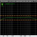 Frequency response
 How to remove problematic Windows updates I can’t remove windows 10 updates