Disk indicator. HDD activity indicator
Introduction
The loading indicators that I will talk about are not only an improvement in appearance, but also have purely practical benefits.
This article consists of two independent parts: the CPU and HDD load indicator.
Hard drive loading indicator
Before starting to create the indicator, I decided to look for the most optimal scheme. Scrolling through a number of sites, I found a relatively small variety of schemes. One of the most important criteria is to get a quality mod for relatively little money. Most circuits use LM3914 microcircuits, which are not that cheap. Therefore, I began to look for a level indicator microcircuit with an output for 5-8 LEDs. The choice fell on the AN6884 due to its low price and wide availability. This microcircuit has five LEDs at the output, and passes 7mA current through each.
To read the signal, two wires from the motherboard are used, to which the hard drive indication LED located on the front panel is connected. Instead of a LED, an optocoupler input is connected to them (see diagram). Even if the polarity is reversed, nothing will burn. The optocoupler in the diagram is necessary for electrical isolation of the motherboard and indicator circuits (this is primarily needed to protect the motherboard).
At zero load - the phototransistor inside the optocoupler is locked - while C6 is discharged through R11. When the load of the hard drive increases, the phototransistor is open, and C6 begins to charge through it. The voltage at C6 changes in proportion to the load level. Depending on the capacity of C6, the rate of change in the load level changes.
The voltage from C6 is removed through the divider R12, R14. Trimmer resistor R14 is used to change the sensitivity of the indicator.
You can install any LEDs at your discretion. For myself, I have set for three smaller levels - green, and for two large ones - red.
Winchester indicator circuit
Setting up the indicator comes down to setting its sensitivity using R14.
Processor load indicator
When the hard drive indicator was already done, I began to think about the indicator for something else. The choice fell on the processor load indicator.
During the search, two options were found - through LPT and through COM.
I chose the COM port only because it was not used, unlike LPT. In the process of searching, I found an article by Clear66, in which he talked about connecting a car tachometer to a COM port. I liked this idea most of all because there is no need to make special circuits for converting digital values into an analog signal. For control, the PCTach program is used (the download link is at the end of the article).
But since at that moment there was not at least some tachometer at hand, I had to make a homemade version of the factory one. After assembly and configuration, the processor load indicator began to show more or less accurately.
But I did not like the increased speed of displaying the load level, which was expressed by excessive jerking of the indicator arrow when the processor load was uneven. But this was corrected by adding an additional capacitor in parallel with the microammeter.
The type of the dial indicator did not suit me much, and I decided to look for an alternative to it. Ultimately, the indicator became LED, and not a scale of LEDs, but two LEDs of different colors directed towards each other. The display of the load level value is made by smoothly changing the brightness of the LEDs.
To make the indicator, I used 4-5mm plexiglass and two LEDs: red and blue. A strip with dimensions of 150mm by 15mm is cut out of plexiglass. After that, along the edges of the strip, places are cut out for the LEDs. The ends and one side of the strip must be sanded with zero emery paper to a uniform matt state. This is necessary for uniform light diffusion. A strip of foil is glued to the reverse side (which is not processed with sandpaper) and on the sides of the strip to reflect the rays of the LEDs. When the strip is ready, the LEDs are glued.
Arrangement of LEDs in a plexiglass strip
When the LEDs are already glued, electrical tape or self-adhesive tape is glued to the ends of the strip. This is necessary so that the LEDs shine only in the desired part of the strip.
The blue above symbolizes cold, i.e. low processor load. Red at the bottom symbolizes heating, i.e. large load. The processor load is proportional to the transition of colors among themselves. The wires going to the board and the 68-100 Ohm resistor are fixed on one edge of the strip with hot melt glue.
To smoothly change the brightness of the LEDs, a PWM signal generation circuit is used. With this control method, the brightness of the LEDs changes from the ratio of the lighting time and the time when it is not lit. This method is better for voltage control in that the brightness of the LEDs changes in proportion to the voltage.
The scheme consists of the following blocks:
voltage driver for DA1.1
sawtooth signal generator on DA2
voltage comparison unit for DA1.2 DA1.3
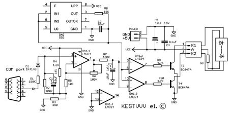
Resistor divider R4, R3 sets the voltage to 1.2 volts, which is approximately equal to the minimum voltage of DA2 sawtooth pulses. The pulses are taken from the third pin of the COM port of the computer. When the input level is high, the capacitor C1 is charged through the resistor R1 and the diode D1. When the input level is low, capacitor C1 is discharged through R2. At C1, a voltage is generated that is proportional to the processor load level. Since the amplitude of this voltage is less than the amplitude of the sawtooth pulses DA2, there is an amplifier on DA1.1 in the circuit. The maximum level of the meter is adjusted by changing the gain with R6. The R7, C3 chain finally smooths out the voltage ripple from the amplifier output. PWM is generated by comparing the measured voltage and sawtooth pulses.
DA1.2 generates a direct, and DA1.3 an inverted PWM signal. These two signals are then fed to LEDs, pre-amplified with switches on transistors T3, T4.
Processor indicator circuit
Execution
Since both indicators are located on the front panel, I made a common board for them. On one edge of the board, there are two stripe tracks. Two M3 nuts are soldered to these strips. Two 3mm holes are drilled in the front of the case frame so that they correspond to the distance between the centers of the nuts on the board. Further, two M3 screws are screwed into these nuts on the board, which pass through the holes in the frame.


Processor load indicator with different load levels:


Hard drive loading indicator with different loading levels:


Long ago, all desktops and laptops had LEDs that blinked when hard drive activity was detected. Over time, computer manufacturers decided that this was not necessary, but I disagree with this: if the computer suddenly does not respond, it can help to find out if there are disk accesses. If so, it may just be a temporary delay. If not, then you will know to restart your computer.
There are other advantages of having such an indicator, of course, but computers are less and less equipped with it. Fortunately, there is a software solution: TrayStatus, a free Windows utility from BinaryFortress.
TrayStatus actually offers a number of monitoring functions, most of them reflect information about the state of the keyboard. So you can see the icon light up when you press, say, Caps Lock or Num Lock. For our purposes, however, let's focus on the hard drive indicator.
Step 1: Download, install and run TrayStatus. (Latest version, 2.0, includes support for Windows 10.)
Step 2: Find the TrayStatus icon in the system tray, right click on it and select "TrayStatus Settings".
Step 3: Make sure "Show Hard Drive Activity" is checked, click "OK".

Step 4: You should see a TrayStatus hard drive icon in your system tray. It will blink green when reading and red when writing. However, by default, this new icon is usually hidden in the system tray, and is only accessible by pressing an arrow, which is hardly convenient. In this case, you can delve into the Windows settings as described in the following steps.
Step 5: In Windows 10 (this process may be slightly different in earlier versions), click Start> Settings. Then select "System", then "Notifications & Actions".

Step 6: Click the Select the icons displayed in the taskbar link and then scroll down until you find TrayStatus Hard Drive. Press the toggle switch to set it to "On". (Other TrayStatus indicators can also be enabled here).
The LED indicator (Light Emiting Diode, LED) of the hard drive (it can be green, yellow or red) is usually located on the front panel of the case and serves to monitor the operation of the hard drive. Each call to the hard drive is accompanied by the lightning of an indicator, usually Indicators, switches and connectors 33
designated on the control panel of the system unit as HDD. Do not be intimidated by the fact that the hard drive indicator is not constantly on, but flashes periodically. The point here is not bad contact, but the visual display of quick access to the hard drive.
PC on indicator
The PC power-on indicator should always light up when the computer is turned on. The cable for this indicator is marked green in most cases. This is a two-wire cable that ends with a three-pin plug, with the middle pin not being used. The color of the cable corresponds to the color of the indicator - green-black or green-white cable.
Typically, the PC power-on indication cable is combined with the KeyLock cable (PC keyboard lock cable). In this case, the cable is supplied with a five-pin connector. As a rule, motherboard manufacturers sign all the places where connectors are connected to the motherboard, so the corresponding terminal can be found without problems. The KeyLock connector can be easily identified even without the markings. Look on the motherboard for a five-pin single row bracket, with one of the five pins missing. This missing pin is a kind of key for the correct connection of the connector.
Since this plug does not have guides, it is very likely that it will be plugged in incorrectly. This error will result in no indication of operation. In this case, you need to turn the plug 180P.
Power switch Normally, a power switch is already connected to the power supply. If this is not the case, you should follow the instruction manual and connect it.
Attention!
When buying, pay attention to the fact that the switch is connected to the power supply. If there are no instructions, then entrust the connection of the power switch to a specialist. Due to the wide variety of power supplies, there is no uniform color coding for the power switch terminals. Be extremely careful when connecting it! We are talking about a network voltage of 220-240 V.
By turning on the computer using the network switch, a cold start of the PC is carried out, that is, the system is started from a rest (cold state). With a cold start, wait at least half a minute before turning on the computer again, since the mechanics of the drives require a certain amount of time to stop completely.
Attention!
Frequent turning on and off the computer without pauses using the power switch can seriously damage the disk drives and hard drive.
After turning on the PC, a self-test of the power supply is performed for about 0.3-0.5 seconds. If all levels of supply voltages are within acceptable limits, the Power_Good signal is sent to the motherboard. This signal is fed to the motherboard, where the initial processor setup signal is generated by the clock generator chip.
In the absence of a PowerGood signal, the clock generator chip will continually supply the CPU with a bootstrap signal, preventing the PC from operating under "abnormal" or unstable supply voltages. When a Power Good signal arrives at the generator, the processor initial setup signal will turn off and the PC (Power On Self Test, POST) program written in the ROM BIOS will start executing. After successful completion of testing, the system will boot.
In some cheap power supplies, there is no Power Good signal conditioning circuit at all, and this circuit is simply connected to a +5 V supply voltage.
Some motherboards are more susceptible to incorrect Power Good signal than others. Starting problems often arise precisely because of the lack of delay in this signal. Sometimes after replacing the motherboard, the PC stops starting normally. In such a situation it is quite difficult to understand, especially for an inexperienced user who thinks that the reason lies in the new board. But do not rush to write it off as faulty, because it often turns out that the power supply is "to blame": either it does not provide enough power to power the new motherboard, or the Power Good signal is not supplied or the Power Good signal is incorrectly generated. In such a situation, it is best to try connecting the motherboard to a different power supply.
Who has not happened to: leave the computer, return in a few minutes - and the hard disk activity indicator blinks. What is he doing there? It looks, of course, very suspicious.But in fact, there is most likely no need to worry. Computers with standard Windows settings do this all the time. Although, of course, the likelihood of infection cannot be ruled out, so it will not hurt to check the system with an antivirus for your own peace of mind.
The computer politely waits for its turn
In reality, the computer does not at all try to secretly do nasty things from the owner. On the contrary, he tries to be smart and polite. Windows requires a variety of service tasks to run in the background, and to start them, the system patiently waits for downtime (that is, user exit). This ensures that computer resources are not wasted on extraneous matters when the user needs to work. If the system is actively used, background service processes are suspended so as not to degrade performance.
So it's not a game of imagination: Windows really does wait for downtime to begin servicing. And when the user returns, the execution of service tasks usually stops, so it is usually not possible to find out why the hard disk activity indicator blinked when inactive. Windows Scheduler allows you to configure the launch of a task exclusively during idle time, and many tasks are performed this way.

What is the computer busy with when it is idle?
But what exactly is the computer doing in the background? The specific set of tasks depends on the system settings and installed programs, but you can list the most common options.
File indexing. All modern operating systems are equipped with a file indexing function. They check each file (including its contents) and create a database, which then instantly returns results when searched. For the search to work, the indexing service must regularly monitor file changes, and this may account for hard drive activity during downtime.
Disk Defragmenter. In the days of Windows 98, you had to close all other programs to successfully defragment your hard drive. Modern versions of Windows defragment automatically in the background, but only when idle.
Scheduled anti-virus scanning. Many antivirus and other security products are set by default to automatically scan your system on a regular basis. Perhaps the activity of the hard disk is due to the fact that the antivirus is just checking the files stored on it.
Backup. If automatic backup is enabled (and should have been enabled!), Hard disk activity may be caused by the file archiving process.
Automatic update. Windows itself and many programs such as Google Chrome or Mozilla Firefox have an automatic update feature. If the computer is busy with something while idle, it is quite possible that it is just downloading and installing updates.
Of course, this is by no means a complete list. The options can be endless, depending on the specific set of installed programs. For example, if the Steam client is open in the background and an update has just been released for one of the games, hard disk activity may be due to downloading and installing this update. Download programs such as BitTorrent clients can also cause disk activity.

How to find out what programs are using the disk when idle
In theory, everything is clear, but how to find out what the computer does in practice? First of all, if there is a suspicion of infection, it is worth scanning the system with a reliable antivirus, not relying solely on the built-in tools. But if you just want to track disk activity, this can also be done.
You can find out which processes are using the disk using the Task Manager and Resource Monitor built into Windows. This is especially true if the disk activity indicator is constantly blinking, and the computer's performance has dropped for some unknown reason.
To open Task Manager, right-click on the taskbar and select Task Manager, or press ++. In Windows 8, the disk load is displayed directly in the Task Manager - you can click on the Disk column to sort processes by this parameter and see which one is using the disk the most.

In Windows 7, this is not possible, so you need to open the Performance tab and click the Open Resource Monitor link. In the Resource Monitor window, go to the "Disk" tab - and you will see a list of processes that can be sorted by the degree of disk load. By the way, in Windows 8 / 8.1 the Resource Monitor also provides much more information than the Task Manager.

To track disk activity over time, you can use Process Monitor from SysInternals, a developer of useful utilities loved by advanced Windows users. You can start Process Monitor and leave it running while it is idle. Then, returning to your computer, you can see exactly which process used the hard drive in your absence.
Process Monitor logs any activity, but using the buttons on the panel, you can filter the list so that only events related to the file system are displayed. For example, in the screenshot below, you can see that disk activity is caused by file indexing.
Process Monitor is good because it can show past activity. Even if the process stops using the disk or ends altogether, information about it remains in the log. But it is hardly worth using this utility all the time, because event recording also creates a load on the system and, as a result, reduces performance. It should also be understood that Process Monitor keeps an event log only while it is running: if you run it after a spike in hard disk activity, you will not be able to find out what exactly it was caused by.
 Epson t50 pcb maker printer for pcb maker
 DIY waterproof phone case
 Stand for a smartphone on a car torpedo with your own hands or how to make a car holder for a phone in a car Homemade phone mount in a car