How to check the resistor with a multimeter for serviceability? How to test a variable resistor with a multimeter? Resistor. Variable resistance resistors What can replace a variable resistor
An electrical circuit is impossible without the presence of resistance in it, which is confirmed by Ohm's law. That is why the resistor is rightfully considered the most common radio component. This state of affairs suggests that knowledge of testing such elements can always come in handy when repairing electrical equipment. Consider the key issues related to how to check a conventional resistor for serviceability using a tester or multimeter.
Main stages of testing
Despite the variety of resistors, conventional elements of this class have a linear I–V characteristic, which greatly simplifies verification, reducing it to three stages:
- visual inspection;
- the radio component is tested for a break;
- compliance check is carried out.
If everything is clear with the first and second points, then there are nuances with the last, namely, it is necessary to find out the nominal resistance. Having a schematic diagram, it will not be difficult to do this, but the trouble is that modern household appliances are rarely equipped with technical documentation. You can get out of the created situation by determining the denomination by marking. We will briefly describe how to do this.
Types of markings
On components manufactured during the Soviet Union, it was customary to indicate the denomination on the body of the part (see Fig. 1). This option did not require decoding, but if the integrity of the structure was damaged or the paint burned out, there could be problems with text recognition. In such cases, it was always possible to refer to the circuit diagram, which was completed with all household appliances.
Figure 1. Resistor "ULI", on the case you can see the part rating and toleranceColor coding
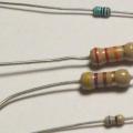
Color marking has now been adopted, which consists of three to six rings of different colors (see Fig. 2). It is not necessary to see the intrigues of enemies in this, since this method allows you to set the denomination even on a badly damaged part. And this is a significant factor, given that modern household electrical appliances are not equipped with circuit diagrams.
 Rice. 2. Example of color coding
 Information on decoding this designation on components is easy to find on the Internet, so it does not make sense to bring it within the framework of this article. There are also many calculator programs (including online ones) that allow you to get the necessary information.
Marking SMD elements
Surface-mounted components (for example, smd resistor, diode, capacitor, etc.) began to be marked with numbers, but due to the small size of the parts, this information needed to be encrypted. For resistances, in most cases, a three-digit designation is adopted, where the first two are the value, and the last is the multiplier (see Fig. 3).
 Rice. 3. An example of decoding the value of the SMD resistor
 Visual inspection
Violation of the normal mode of operation causes overheating of the part, therefore, in most cases, the problem element can be identified by its appearance. This can be either a change in the color of the hull, or its complete or partial destruction. In such cases, it is necessary to replace the burnt element.
 Figure 4. A vivid example of how a resistor can burn out
 Pay attention to the photo above, the component marked "1" clearly needs to be replaced, while the neighboring parts "2" and "3" may be working, but they need to be checked.
Open circuit test
Actions are performed in the following order:

If the model of the device you are using differs from that shown in the figure, read the instructions that came with the multimeter.
- We touch the leads of the problem element on the board with the probes. If the part “does not ring” (the multimeter will show the number 1, that is, an infinitely large resistance), we can state that the test showed an open in the resistor.
Please note that this test can be carried out without unsoldering the element from the board, but this does not guarantee a 100% result, since the tester can show the connection through other components of the circuit.
Denomination check
If the part is soldered, then this stage will allow you to guarantee its performance. For testing, we need to know the value. How to determine it by marking, it was written above.
The algorithm of our actions is as follows:

What is permission, and how important is it?
This value shows the possible deviation of this series from the specified face value. In a correctly calculated scheme, this indicator must be taken into account, or after assembly, the corresponding adjustment is made. As you understand, our friends from China do not bother with this, which has a positive effect on the cost of their goods.
The result of such a policy was shown in Figure 4, the part works for some time until the limit of its safety margin comes.
- We make a decision by comparing the readings of the multimeter with the nominal value, if the discrepancy is beyond the error, the part definitely needs to be replaced.
How to test a variable resistor?
The principle of action in this case is not very different, we will describe them using the example of the part shown in Figure 7.
 Rice. 7. Trimmer resistor (internal circuit marked with red circle)
 The algorithm is the following:
- We carry out a measurement between the legs "1" and "3" (see Fig. 7) and compare the obtained value with the nominal value.
- We connect the probes to the conclusions "2" and any of the remaining ones ("1" or "3", it does not matter).
- We rotate the tuning knob and observe the readings of the device, they should vary in the range from 0 to the value obtained in step 1.
How to check a resistor with a multimeter without soldering on the board?
This testing option is valid only with low-resistance elements. Above 80-100 ohms, it is very likely that other components will interfere with the measurement. The final answer can only be given by carefully studying the circuit diagram.
Schematic diagram of a simple electronic potentiometer, or how to replace a variable resistor with a handle with two buttons for adjustment in different circuits and devices. The device uses field-effect transistors KP304 or KP301.
Sometimes it happens that you need to remake some kind of regulator based on variable resistors with rotating knobs for digital push-button control. The solution of such a problem can be based on a microcontroller, using digital microcircuits, etc.
This article describes a simple solution that will allow you to replace the variable resistor with a small circuit with two buttons: "MORE", "LESS".
In the Radio magazine for 1987 No. 11, a simple timbre block on a microcircuit was described, its feature was electronic timbre control using buttons.
circuit diagram
The circuit is based on a field effect transistor and a capacitor. Using the buttons, we control the degree of charge of the capacitor, the voltage on which controls the field-effect transistor.
Rice. 1. Scheme for replacing a variable resistor with two buttons.
The disadvantage of this adjustment scheme is that there is no memorization of the initial state at the moment of switching on, and also the capacitor still loses its charge after the time has elapsed.
Nevertheless, this solution can perfectly cope, for example, with the task of adjusting the volume in a simple amplifier.
Details and design
The field effect transistor KP304 can be replaced by the transistor KP301. The appearance and pinout is shown in Figure 1. It is also very important to install the correct capacitor C12 in the circuit, it must be energy-intensive, combined capacitors are perfect here.
Combined Capacitors general purpose are made in steel sealed cases (K75-12, K75-24) or in an insulating epoxy case (K75-47) with a rated capacitance up to 10 μF and a rated voltage from 400 Volts to 63 kVolts.
The use of a combined dielectric in such capacitors makes it possible to improve the stability of electrical parameters, extend the range of operating temperatures, and in some cases improve their characteristics compared to paper capacitors.
In this circuit, it is best to use pulsed energy-intensive combined capacitors K75-11, K75-17, K75-40, with a capacity of 0.22 to 1 μF. You can experiment with other types of capacitors, but their efficiency in this circuit, most likely, will not be the best.

Rice. 2. Appearance of K75-11 capacitors.
It is desirable to perform installation on a double-sided foil textolite, one side is for tracks, and the other is a screen with a connection to a common one.
Attention! You need to solder the field-effect transistor very carefully, it is afraid of static voltage, and can also fail in case of overheating.
The result is something like this push-button electronic variable resistor. The circuit is very simple and starts working immediately after switching on.
Using the tuning resistor R23, the desired regulation threshold is set, as well as the initial value of the output voltage.
Often during an external examination, damage to the varnish or enamel coating can be detected. A resistor with a charred surface or rings on it is also faulty. A slight darkening of the varnish coating allowed for such resistors should be checked for the resistance value. Permissible deviation from the nominal value should not exceed ±20%. The deviation of the resistance value from the nominal value in the direction of increase is observed during long-term operation of high-resistance resistors (more than 1 MΩ).
In some cases, a break in the conductive element does not cause any changes in the appearance of the resistor. Therefore, the resistors are checked for compliance with their nominal values using an ohmmeter. Before measuring the resistance of resistors in the circuit, turn off the receiver and discharge the electrolytic capacitors. When measuring, it is necessary to ensure reliable contact between the terminals of the tested resistor and the terminals of the device. In order not to shunt the device, do not touch the metal parts of the ohmmeter probes with your hands. The value of the measured resistance must correspond to the value indicated on the resistor case, taking into account the tolerance corresponding to the class of this resistor and the intrinsic error of the measuring device. For example, when measuring the resistance of a resistor of class I accuracy using the Ts-4324 instrument, the total error during the measurement can reach ±15% (resistor tolerance ±5% plus instrument error ±10). If the resistor is tested without. soldering it out of the circuit, then it is necessary to take into account the influence of shunt circuits.
The most common malfunction in resistors is the burnout of the conductive layer, which can be caused by the passage of an unacceptably large current through the resistor as a result of various short circuits in the installation or breakdown of the capacitor. Wirewound resistors are much less likely to fail. Their main malfunctions (breakage or burnout of the wire) are usually found using an ohmmeter.
Variable resistors (potentiometers) most often have a violation of the contact of the movable brush with the conductive elements of the resistor. If such a potentiometer is used in a radio receiver to adjust the volume, then when turning its axis, cods are heard in the head of the dynamic loudspeaker. There are also breaks, wear or damage to the conductive layer.
The serviceability of the potentiometers is determined with an ohmmeter. To do this, connect one of the ohmmeter probes to the middle petal of the potentiometer, and the second probe to one of the extreme petals. The axis of the regulator with each such connection is very slowly rotated. If the potentiometer is working, then the ohmmeter needle moves along the scale smoothly, without jitter and jerks. The jitter and jerks of the arrow indicate poor contact between the brush and the conductive element. If the ohmmeter needle does not deviate at all, this means that the resistor is faulty. It is recommended to repeat such a check by switching the second probe of the ohmmeter to the second extreme lobe of the resistor to make sure that this output is also working. A defective potentiometer must be replaced with a new one or repaired if possible. To do this, open the case of the potentiometer and thoroughly wash the conductive element with alcohol and apply a thin layer of machine oil. Then it is collected and the reliability of the contact is checked again.
Resistors that are deemed unusable are usually replaced with serviceable ones, the values of which are selected so that they correspond to the circuit diagram of the receiver. In the absence of a resistor with the appropriate resistance, it can be replaced by two (or several) connected in parallel or in series. When two resistors are connected in parallel, the total resistance of the circuit can be calculated by the formula
![]()
where P is the power dissipated by the resistor, W; U is the voltage across the resistor. IN; R is the resistance value of the resistor; Ohm.
It is advisable to take a resistor with a slightly higher dissipation power (by 30,..40%) than that obtained in the calculation. In the absence of a resistor of the required power, you can select several smaller resistors. power and connect them to each other in parallel or in series so that their total resistance is equal to the one being replaced, and the total power is not lower than the required one.
When determining the interchangeability of various types of fixed and variable resistors for the latter, the characteristic of the change in resistance from the angle of rotation of its axis is also taken into account. The choice of the characteristics of the change of the potentiometer is determined by its circuit purpose. For example, in order to obtain a uniform volume control of the radio receiver, you should select the potentiometers of group B (with an exponential dependence of the change in resistance), and in the tone control circuits - group A.
When replacing failed resistors of the BC type, it is possible to recommend MLT type resistors of the appropriate dissipation power, which have smaller dimensions and better moisture resistance. The rated power of the resistor and its accuracy class are not significant in the circuits of the control grids of lamps and collectors of low power transistors.
Electronic circuits sometimes fail. There are many reasons for this, but the point is to change the current modes, which have a destructive effect on the radio elements. Exceeding the permissible ratings of electricity leads not only to the burnout of radio components, it happens that even the current-carrying tracks of the printed circuit board burn out. To restore operability, it is necessary to calculate which components of the circuit have suffered. Therefore, there is a way to check the resistor with a multimeter, as well as other radio components.
What is a radio check?
Checking radio elements is nothing more than measuring their actual performance and comparing them with the technically embedded parameters during manufacture. If the data match or are close in value (within acceptable limits), this indicates the health of the radio components. In the event of a significant discrepancy, the elements are clearly defective and require replacement.
What results can be achieved by measuring the details of the radio circuit:
- Determine fault. This will allow you to restore the circuit after replacing the burnt element with a new one.
- Detect partial wear of the radio component. This will help prevent device failure in the future.
- Reveal a hidden defect. For example, a badly soldered pin that will break off over time, especially if the circuit is subjected to vibration.
- Establish a chain of violations for one failed radio component. In many schemes, the combustion of one particular element automatically leads to the combustion of others dependent on it.
What instrument is used to test resistors?
The resistor, or resistance, is one of the main radio elements, which is necessarily present in any circuit. It limits the current strength, dissipates excess power, removes the voltage drop from it for the operation of electronic keys, it performs a protective function (it works on the principle of a fuse).
Among such devices, the most common are analog (pointer) and digital multimeters. When determining the parameters of the first type of equipment, in addition to the measurement switching limits, they use a graduated scale for an ohmmeter. The use of electronic devices is the easiest way to check a resistor with a multimeter. They display the value of the readings on a digital display.
You can see in the presented photo how to check the resistor with a multimeter.
How to check resistor value?
Usually, radio elements are marked, which tells the installer or repairman about the purpose of the device and its technical parameters. On resistors, this can be a digital or color coding. But sometimes there is absolutely no information on the element itself and on the printed circuit board, and it is not clear how to determine the value of the device, in this case. Checking the resistor with a multimeter in this case is the only possible option.
It is more convenient for these purposes to use an electronic device such as DT830B. It is important to know that it is impossible to make reliable measurements of the resistor value if it is included in the circuit. The reason for this is the property of current to flow along the path of least resistance. And if there is a workaround for it in the circuit, bypassing the measured element, then the device will have anything, but not reliable information. Another reason why an element should be desoldered is the presence of field parts in the circuit, which can fail during the measurement process.
In a schema? Solder at least one of its conclusions. After that, you can carry out the measurement process:

How to test a variable resistor with a multimeter?
On the body of the variable resistor, its value is affixed, and the device itself has three outputs. The nominal value is the value between the extreme terminals of the radio element, the indicator of the average output will change in accordance with the angle of rotation of the adjusting knob. In order not to "anyhow" check the variable resistor with a multimeter, it is not enough to measure its value. It is important to see the nature of the change in resistance between the middle terminal relative to the extreme one when the knob is turned.

The variable resistor also needs to be soldered from the circuit. Once this is done, the measurement steps are as follows:
- Set the measurement limit of the multimeter to a position higher than the nominal value indicated on the case.
- Measure the readings between the extreme conclusions. If the resistance is equal to infinity, the resistor is broken; if it is zero, the element burns out. If the measurement results correspond to the nominal value, the operation of the middle output is checked.
- The resistor adjustment knob is moved to any extreme position, one of the probes of the device is left at the extreme terminal, the other is connected to the middle one. The device should show a resistance close to zero or nominal (depending on the connection side) - this is correct. If the resistance is equal to infinity, then there was a break with the middle output slider. This is an indicator of how to check the health of the resistor with a multimeter.
- Next, the degree of wear of the resistive surface under the slider is determined. To do this, without turning off the device, slowly turn the adjustment knob from one extreme position to another. At the same time, they monitor the readings on the scoreboard - the resistance should change smoothly. If disappearances occur (on the device it corresponds to infinity), then the resistive layer is partially worn out, and the radio element needs to be replaced.

How to check the resistor with a multimeter for serviceability?
As a rule, not all elements in a row are checked with the device, but those that are suspicious. They may be darkened, with traces of peeling paint and other visible irregularities. To reliably determine whether the radio component is working or not, you need:
- Measure the value of the resistor and compare with the declared value on the case. The deviation of the readings should not exceed the allowable percentages, which are also indicated on the element.
- Having connected the probes, it is necessary to slightly move the conclusions of the radio element. If the readings suddenly begin to disappear, then appear, this is a sure sign of a hidden defect.

How, without soldering, to check the resistor in the circuit?
There are resistors that come with leads, there are leadless SMD elements. Soldering the latter from the printed circuit board is difficult without a special soldering iron nozzle. Therefore, the parameters of such radio components are measured directly in the circuit. How to check a resistor with a multimeter without soldering:
- Carefully inspect the printed circuit board and find a track on it that extends from any output of the SMD resistor without taps.
- Carefully cut it in a place with the least thickening.
- Measure the radio element with a device.
- After we checked the resistor with a multimeter on the board, and it turned out to be faulty, replace it and solder the jumper at the break point.
How to determine the permissible measurement error?
On the case of each resistor there is information about the nominal deviations. It can be written as 5%, 10%, 20% or hidden in color coding. For a normal serviceable radio element, when measuring its face value, the readings will not go beyond the allowable percentage.
Conclusion
It is easy to figure out how to check a resistor with a multimeter, but you should not climb into complex devices containing many microcircuits with the device. It is much cheaper in this case to entrust the work to an experienced master.
As you know, variable resistors, which in all kinds of audio equipment are used to adjust the volume, tone and other stereo balance, wear out over time. And when the knobs are turned, wheezing, crackling, clicking, and other non-musical sounds are heard from the speakers.
Moreover, as they wear out, their volume changes from a barely noticeable rustle to a crackle quite comparable with the level of a useful signal.
Now, when musical equipment with digital push-button control has flooded into the market, for many music lovers the problem has become a thing of the past.
But even now there are still many music lovers who prefer to listen to it through the good old Soviet, imported or home-made amplifier with good old alternators.
I hope that this article will be useful to some of you. Although it is possible that once again I undertake to explain the obvious things with a smart look.
The time comes and the regulator, which has faithfully served for more than a dozen years and sometimes outlived the device itself, in which it was originally installed, begins to wheeze. Usually Soviet variable resistors are scolded for this. But, sooner or later, trouble overtakes the regulator, regardless of the country of origin.
The one who undertook to eliminate this trouble has two ways to solve the problem. Try to return the old variable to working capacity or replace it with a new one.
Replace, of course, a good way out, but what?
If you're lucky, in a pile of spare parts accumulated by a radio amateur from time immemorial, you can find another such variable or with similar parameters. But where is the guarantee that he will not wheeze soon. By age, he, perhaps, is almost the same age as the one being replaced and it is not known where he stood, how often he was twisted and in what conditions the device was operated.
If there is a store nearby, or some other institution selling radio components, you can buy there the product of the “fraternal narrow-eyed republic”, which is a trimmer, to which the body and axle were hastily attached. Such a resistor is usually practically not protected from dust, moisture and other external debris. And the conclusions are sometimes riveted to the carbon "horseshoe" so that they hang out even at the new resistor, guaranteeing the same wheezing, crackling and loss of sound.
Perhaps somewhere closer to civilization you can get a quality part, but judging by the prices in music stores, where alternators for electric guitars are sometimes sold, the price can be a very large fraction of the price of the repaired product itself.
An autopsy will show. Potentiometer SPZ-30 from the inside
From the point of view of ease of repair, I divide variable resistors into three types - collapsible, conditionally non-collapsible and almost non-collapsible.I'll start with the simplest - collapsible. For example - SPZ-30a, as it is quite large and often found. In addition, in my opinion, it is generally one of the best variables created in the USSR. At least in terms of such parameters as protection against "outboard debris" and maintainability. And with shortcomings, such as “incomplete zeroing” in extreme positions, or a mismatch of resistances (in dual ones) between the engine and the extreme conclusions during adjustment, it is quite possible to put up with sound technology.
Most tips will fit older SP-1s, VZRs, either single or twin.
Close-up portrait of the "beast". I apologize for the quality of the photos - I shot directly during the "operation", a year ago, with a camera that was at hand, without bothering with the settings and lighting.

We will assume that the resistance between the extreme terminals is measured, exists, does not greatly exceed that indicated on the case and does not “float”. Otherwise, the part can be safely thrown away, well, or put into spare parts. Somewhere in the literature I met a method of manufacturing from SP3 parts, a small-sized multi-position switch.
We bend 4 antennae, marked with arrows, and remove the cover. We admire the simple inner world:

In the meantime, a small "lyrical digression."
Almost everyone who has connected his life with amateur radio, sooner or later, all acquaintances, relatives, relatives of acquaintances and acquaintances of relatives drag their dead equipment for repair. It happens that because of the "hoarse" regulator.
Bringers fall into two categories.
1. Ordinary users - as a rule, they carry their device as soon as the malfunction has made itself felt.
2. More or less advanced users - before bringing, they try to fix it themselves, using their "knowledge" or the advice of "knowledgeable".
From such people I often heard something like this monologue: “I tried to do it myself. I wiped it with alcohol, vodka, “triple cologne”. He dripped with oil, rubbed a horseshoe with a pencil, mixed a crushed pencil with oil and dripped. A couple of days and again the same thing. Do something! It's fucked up, damn it!!!"
This is how the usual tips look like, which are walking among the people and even sometimes help (otherwise they would not have walked).
Indeed - looking at the coal “horseshoe” stained with old blackened grease, the first thought that comes to mind is to clean all this economy right like that - through the gap between the dielectric washer dressed on the shaft and the wall of the plastic case.
But still it is better to continue the disassembly. And access to the surfaces to be cleaned will be better, and there you look - and something else interesting will be found.
Unfolding the thrust ring:

And we pull out the axis, together with a textolite washer with a movable contact fixed on it.
Immediately carefully consider the state of the coal layer on the "horseshoe".

In this case, it is well preserved. So, there is some sense in further actions. If it has worn off so much that a textolite base is visible in the place where graphite should be, “medicine is powerless”. Although, to be honest, since the 80s I have met only two (!) So worn-out variables. One of them was in the Mayak-232 tape recorder, which worked in one of the schools. There, apparently due to a factory defect, the carbon brush on the movable contact crumbled and the horseshoe was simply worn off with a metal spring electrode. I thought so, because the variable was dual, and the second resistor of the block was still quite normal. The tape recorder at that time was ten years old, if not more.
Now the surface of the horseshoe can, and even needs to be cleaned of “age-old dirt” (especially after “crushed pencil in oil”) with alcohol or pure gasoline for lighters. At the same time, you need to clean the spring contacts connecting the central output to the engine.
And then carefully look at the surface on which these contacts should slide:

Even with this quality of the photo, you can see that this place looks, to put it mildly, scary. The contacts have rubbed a noticeable "trench", which, due to the layer of lubricant, seems deeper than it actually is. And if you take a closer look, you can see that the metal surface is smeared somewhere, oxidized somewhere, and sees reliable contact only in dreams of bygone youth.
We clean the metal from the old, sometimes hardened to a complete resemblance to paraffin, grease and dirt, graphite dust. If necessary, clean the oxide with an eraser. It's a pity the good old Soviet red erasers can no longer be found. And how many deuces they had in the diary wiped out to make it easier to correct by triples. And the contacts in television PTKs have been cleaned (often in vain). I generally keep quiet about other toggle switches and P2K.
It's time to tackle the moving contact carbon brush

For a "long happy life" worn out, of course. It’s a pity there is no completely new variable of the same type at hand to clarify how much. Therefore, I often assessed the degree of wear “by eye”.
If about one millimeter is left - it will still live, if less than 0.5 mm - he made a new one from a pencil lead, or a carbon rod from a discharged AA battery that accidentally turned up. I usually cut it with the knife that was at hand at that moment, then leveled the contact surface on the file. Something similar was once described in Radio magazine.
As for the material: I once met a dispute on the Web, which is better - a carbon rod from a battery or a pencil. And if a pencil, then what hardness. I haven't come to a definite conclusion yet. What I did for myself so far works well. And he used mainly those pencils that he himself used at that moment, with a hardness somewhere at the level of “TM” - “T”. And the hardness of carbon rods from batteries, who knows.
Before installing the brush in its rightful place, I did one more thing. The tip of the spring contact, approximately from the hole for the brush, was bent at a small angle (green arrow in the photo). And also grinded off the burrs on the edges of this hole and the ends of the spring, if any, with a fine sandpaper, a file or, in extreme cases, with a knife. Somehow calmer later, although I'm not sure of the real benefits of this action.
Before the final assembly, all rubbing surfaces were lubricated with engine oil (the thickest that was available), If possible, with Litol or CIATIM. Something else in our area is more difficult to get.
After such procedures, all extraneous sounds usually disappear for a long time.
A little about SP-1

Recently, one device fell into the hands, where the great and terrible ... SP-1 was used to adjust the volume. And the same problem with wheezing crackling and loss of sound.
So, it became possible to talk about one of its differences from SP3, which can very much cause problems, and which you can not immediately pay attention to. In the tape recorder that I had in school days, I fiddled with the volume control several times until I accidentally stumbled upon it.
By the way, the disassembly is exactly the same as in the previous example.
But unlike SP3, SP-1 has a fixed contact, riveted to the central terminal, not spring, but flat, annular. This very contact lies calmly in the groove intended for it. And if you don’t move it on purpose, then you may not even notice that it sometimes hangs freely on the rivet.

And this contact between the output and the variable engine appears and disappears of its own accord. It is possible that there are also SP3 with a central contact dangling on the rivet, but I have not come across such ones yet.
To fix the problem, as many guessed, it is enough to solder this connection. For greater reliability, you can also solder from the output side, although most often this is not required.
By the way, the carbon layer is very well preserved for a variable resistor with metal brushes from the device of the late 70s.
These are fairly simple recommendations for returning wheezing variable resistors to active life. True, here I have considered only one type, but I repeat - others differ only in the way of disassembly-assembly. The components and locations of possible faults are the same.
P.S. It happens that you can buy a new variable with the described defect. It is not known how long, where and under what conditions it was stored before. Even if it looks like new.
Just in case, before installing in the product, it is worth doing the above operations. The anecdote about “finishing with a file” was not just invented for nothing. I myself have several times encountered the fact that a “fresh” regulator “rustles” when the engine approaches extreme points. Usually, after cleaning and lubrication, the "disease" disappears. I recently put freshly bought small-sized SPZ-40 into the tone block of an electric guitar, and immediately I had to remove all four resistors again and carry out the same procedures.
Since then, it has been running for two years with no problems.
Reader's vote

 How to test a variable resistor with a multimeter?
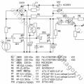 What are bathroom timers, and how to make a fan with a do-it-yourself timer?
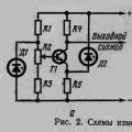 Voltage relay test