How to disassemble the power supply of an apple laptop. How to Quickly Fix a Frayed MacBook Charge Cable
Fair, not too high or too low. There should be prices on the Service website. Necessarily! without "asterisks", clear and detailed, where it is technically possible - the most accurate, final.
If spare parts are available, up to 85% percent of complex repairs can be completed in 1-2 days. Modular repairs take much less time. The site indicates the approximate duration of any repair.
Warranty and Liability
A warranty should be given for any repair. Everything is described on the site and in the documents. A guarantee is self-confidence and respect for you. A 3-6 month warranty is good and enough. It is needed to check the quality and hidden defects that cannot be detected immediately. You see honest and realistic terms (not 3 years), you can be sure that you will be helped.
Half the success in Apple repair is the quality and reliability of spare parts, so a good service works directly with suppliers, there are always several reliable channels and a warehouse with proven spare parts for current models so that you do not have to waste extra time.
Free diagnostics
This is very important and has already become a rule of good form for the service center. Diagnosis is the most difficult and important part of the repair, but you should not pay a dime for it, even if you do not repair the device after it.
Service repair and delivery
A good service values your time, so it offers free shipping. And for the same reason, repairs are carried out only in the workshop of the service center: it can be done correctly and according to technology only at a prepared place.
Convenient schedule
If the Service works for you, and not for itself, then it is always open! absolutely. The schedule should be convenient in order to be in time before and after work. Good service works on weekends and holidays. We are waiting for you and working on your devices every day: 9:00 - 21:00
The reputation of professionals consists of several points
Age and experience of the company
Reliable and experienced service is known for a long time.
If a company has been on the market for many years, and it has managed to establish itself as an expert, they turn to it, write about it, recommend it. We know what we are talking about, since 98% of incoming devices in the SC are restored.
We are trusted and passed on complex cases to other service centers.
How many masters in the directions
If you are always waiting for several engineers for each type of equipment, you can be sure:
1. there will be no queue (or it will be minimal) - your device will be taken care of immediately.
2. You give Macbook repair to an expert specifically in the field of Mac repairs. He knows all the secrets of these devices
technical literacy
If you ask a question, the specialist must answer it as accurately as possible.
To give you an idea of what you need.
Will try to solve the problem. In most cases, from the description, you can understand what happened and how to fix the problem.
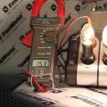
Mechanical damage usually reveals an external examination. In the case of our power supply, the problem was with the cable at the base of the magnetic connector. If the cable looks intact on the outside, then the damage may be inside the insulation or connector.
Be careful and try not to use a faulty power supply, it can be dangerous for your laptop and your health!
We proceed to replace the cable with a new one. To do this, you will need to disassemble the power supply and replace the old cable with a new one by soldering it.

Step 2 - Disassembling the Power Supply
To gain access to the insides of the power supply, it is necessary to separate the two halves that make up the block body. The halves are glued together, so you have to use force.We open the brackets designed for winding the cable when transporting the unit. We insert the pliers, as shown in the illustration, and unclench them with a little effort until the body halves begin to diverge from each other. We repeat the procedure on the other side.

Step 3 - Preparing the cable for desoldering
Next, we open the case completely. 
Step 4 - Preparing the cable for desoldering
Carefully open the copper shield covering the insides of the power supply. 
Step 5 - Cutting the Cable
Be careful, the screen is attached to the board with one leg, do not damage it. 
Step 6 - Soldering the cable
We solder the cable wires from the board. To simplify soldering, we recommend using soldering acid. Next, solder the new cable. 
Step 7 - Assembling the Power Supply
We assemble the halves of the power supply using glue for plastic products. We use universal super glue brand "Moment".For convenience, we used the Spudger tool, which applied glue to one of the halves of the block.
Have you ever wondered what is inside the MacBook charger? There are far more parts in the compact power supply than you might expect, including even a microprocessor. In this article, you and I will be able to disassemble the MacBook charger to see the many components hidden inside and find out how they interact to safely deliver much-needed electricity to the computer.
Most consumer electronics, from your smartphone to your TV, use switching power supplies to convert the AC power from the wall outlet to the low-voltage DC used by the electronic circuits. Switch mode power supplies, or more correctly secondary power supplies, get their name from the fact that they turn the power supply on and off thousands of times per second. It is the most efficient for voltage conversion.
The main alternative to the switching power supply is the linear power supply, which is much simpler and converts surge voltage into heat. Due to this energy loss, the efficiency of a linear power supply is about 60%, compared to about 85% for a switching power supply. Linear power supplies use a bulky transformer that can weigh up to a kilogram or more, while switching power supplies can use tiny high frequency transformers.
Now these power supplies are very cheap, but this was not always the case. In the 1950s, switching power supplies were complex and expensive, used in aerospace and satellite applications that needed a light and compact power supply. By the early 1970s, new high-voltage transistors and other technological improvements had made batteries much cheaper and were widely used in computers. The introduction of single-chip controllers in 1976 made power converters even simpler, smaller, and cheaper.
Apple's use of switching power supplies began in 1977, when chief engineer Rod Holt designed the switching power supply for the Apple II.
According to Steve Jobs:
This switching power supply was as revolutionary as the Apple II logic. Rod did not receive much recognition in the pages of history, but he deserved it. Every computer now uses switching power supplies, and they are all similar in design to Holt's design.
It's a great quote, but it's not entirely true. The power supply revolution happened much earlier. Robert Boschert started selling switching power supplies in 1974 for everything from printers and computers to the F-14 fighter jet. Apple's design was similar to earlier devices and other computers did not use Rod Holt's design. However, Apple is making extensive use of switching power supplies and pushing the boundaries of charger design with compact, stylish and advanced chargers.
What's inside?
The Macbook 85W charger model A1172 was taken for analysis, the dimensions of which are small enough to fit in the palm of your hand. The figure below shows a few features that can help distinguish an original charger from fakes. A bitten apple on the case is an essential attribute (which everyone knows about), but there is a detail that does not always attract attention. Original chargers must have a serial number located under the ground contact.

As strange as it may sound, the best way to open the charge is to use a chisel or something similar and add a little brute force to it. Apple was initially opposed to someone opening up their products and inspecting the “insides”. Removing the plastic case, you can immediately see the metal heat sinks. They help cool the powerful semiconductors housed inside the charger.

On the back of the charger, you can see the printed circuit board. Some tiny components are visible, but most of the circuitry is hidden under a metal heatsink held together with yellow electrical tape.

We looked at the radiators and that's enough. To see all the details of the device, of course, you need to remove the heat sinks. There are far more components hidden under these metal parts than one would expect from a small block.

The image below shows the main components of the charger. AC power enters the charger and is already converted to direct current there. PFC (Power Factor Correction) circuitry improves efficiency by ensuring a stable load on the AC lines. In accordance with the feasible functions, it is possible to divide the microcircuit into two parts: primary and secondary. The primary part of the board, together with the components placed on it, is designed to lower the high-voltage direct voltage and transfer it to the transformer. The secondary part receives a constant low-voltage voltage from the transformer and outputs a constant voltage of the required level to the laptop. Below we consider these schemes in more detail.

AC input to charger
The alternating voltage is supplied to the charger through a detachable mains cable plug. A big advantage of switching power supplies is their ability to operate over a wide range of input voltages. By simply changing the plug, the charger can be used in any region of the world, from European 240 volts at 50 GHz to North American 120 volts at 60 GHz. Capacitors, filters and inductors at the input stage prevent interference from leaving the charger through the power lines. The bridge rectifier contains four diodes that convert AC power to DC.
Watch this video for a better demonstration of how a bridge rectifier works.

PFC: power smoothing
The next step in the operation of the charger is the power factor correction circuit, marked in purple. One problem with simple chargers is that they only get charged for a small portion of the AC cycle. When a single device does this, there are no particular problems, but when there are thousands of them, it creates problems for energy companies. This is why regulations require chargers to use power factor correction (they use power more evenly). You might expect poor power factor to be caused by switching power transmission that turns on and off quickly, but this is not a problem. The problem comes from the non-linear diode bridge, which only charges the input capacitor when the AC signal peaks. The idea behind the PFC is to use a DC boost converter before switching the power supply. Thus, the current sine wave at the output is proportional to the AC waveform.
The PFC circuit uses a power transistor to accurately churn the AC input tens of thousands of times per second. Contrary to expectations, this makes the load on the AC lines smoother. The two largest components in a charger are the inductor and the PFC capacitor, which help boost the DC voltage to 380 volts. The charger uses the MC33368 chip to run the PFC.
Primary power conversion
The primary circuit is the heart of the charger. It takes the high DC voltage from the PFC circuit, chops it up, and feeds it into a transformer to generate a charger low voltage output (16.5-18.5 volts). The charger uses an advanced resonant controller that allows the system to operate at very high frequencies up to 500 kilohertz. The higher frequency allows more compact components to be used inside the charger. The IC shown below controls the power supply.
SMPS controller - high voltage resonant controller L6599; labeled DAP015D for some reason. It uses a half-bridge resonant topology; in a half-bridge circuit, two transistors drive power through the converter. Common switching power supplies use a PWM (Pulse Width Modulation) controller that corrects the input time. L6599 corrects the frequency of the pulse, not its pulse. Both transistors turn on alternately for 50% of the time. When the frequency increases above the resonant frequency, the power drops, so the frequency control adjusts the output voltage.

The two transistors alternately turn on and off to lower the input voltage. The transducer and capacitor resonate at the same frequency, smoothing the interrupted input into a sine wave.
Secondary power conversion
The second half of the circuit generates the output of the charger. It receives power from the converter and with the help of diodes, converts it into direct current. Filter capacitors smooth out the voltage that comes from the charger through the cable.
The most important role of the secondary part of the charger is to store dangerous high voltage inside the charger in order to avoid potentially dangerous shock to the end device. The insulation boundary, marked with a red dotted line in the image above, indicates the separation between the main high voltage part and the low voltage secondary part of the device. Both sides are separated from each other by a distance of about 6 mm.
The transformer transfers power between the primary and secondary devices using magnetic fields, instead of a direct electrical connection. The wire in the transformer is triple insulated for safety. Cheap chargers tend to be stingy with insulation. This poses a security risk. An optocoupler uses an internal light beam to transmit a feedback signal between the secondary and primary parts of the charger. The control circuit in the primary part of the device uses the feedback signal to adjust the switching frequency to keep the output voltage stable.

Powerful microprocessor inside charger
The unexpected component of the charger is a miniature circuit board with a microcontroller, which can be seen in our schematic above. This 16-bit processor constantly monitors charger voltage and current. It enables transmission when the charger is connected to the MacBook and disables transmission when the charger is disconnected. Disconnecting the charger occurs if there is any problem. This is a Texas Instruments MSP430 microcontroller, about the same power as the processor inside the first original Macintosh. The processor in the charger is a low power microcontroller with 1 KB of flash memory and only 128 bytes of RAM. It includes a high-precision 16-bit A/D converter.
The 68,000 microprocessors from the original Apple Macintosh and the 430 microcontrollers in the charger are not comparable because they have different designs and instruction sets. But for a rough comparison, the 68000 is a 16/32 bit processor running at 7.8MHz, while the MSP430 is a 16 bit processor running at 16MHz. The MSP430 is designed for low power consumption and uses approximately 1% of the 68000's power supply.

The square orange overlays on the right are used to program the chip during production. The 60W MacBook charger uses an MSP430 processor, but the 85W charger uses a general purpose processor that needs to be flashed. It is programmed with the Spy-Bi-Wire interface, which is a two-wire version of the TI standard JTAG interface. Once programmed, the safety fuse in the chip is destroyed to prevent the firmware from being read or modified.
The three pin IC on the left (IC202) reduces the charger's 16.5 volts to the 3.3 volts required by the processor. The voltage to the processor is provided not by a standard voltage regulator, but by the LT1460, which delivers 3.3 volts with an exceptionally high accuracy of 0.075%.
Lots of tiny components on the underside of the charger
Flipping the charger upside down on the circuit board reveals dozens of tiny components. The PFC and Power Supply Controller Chip (SMPS) are the main integrated circuits that control the charger. The voltage reference chip is responsible for maintaining a stable voltage even when the temperature changes. Voltage reference chip, it is TSM103/A which combines two operational amplifiers and a 2.5V reference in a single chip. The properties of a semiconductor vary greatly with temperature, so maintaining a stable voltage is not an easy task.
These microcircuits are surrounded by tiny resistors, capacitors, diodes and other small components. MOS - output transistor, turns the power on and off at the output in accordance with the instructions of the microcontroller. To the left of it are resistors that measure the current being sent to the laptop.

An isolation boundary (marked in red) separates the high voltage from the low voltage output circuit for safety. The dotted red line shows the insulation boundary that separates the low voltage side from the high voltage side. Optocouplers send signals from the secondary side to the main device, turning off the charger if there is a problem.
A little about grounding. A 1KΩ ground resistor connects the AC ground terminal to the ground at the output of the charger. Four 9.1MΩ resistors connect the internal DC base to the output base. Since they cross the isolation boundary, security is a concern. Their high stability avoids the danger of shock. The four resistors are not really required, but the redundancy is there to ensure the safety and fault tolerance of the device. There is also a Y capacitor (680pF, 250V) between internal ground and output ground. T5A fuse (5A) protects the ground output.
One of the reasons to install more control components in the charger than usual is the variable voltage output. To deliver 60 watts of voltage, the charger provides 16.5 volts with a resistance level of 3.6 amps. To deliver 85 watts, the potential rises to 18.5 volts and the resistance is 4.6 amps, respectively. This allows the charger to be compatible with laptops that require different voltages. As the current potential rises above 3.6 amps, the circuit gradually increases the output voltage. The charger will shut down automatically when the voltage reaches 90W.
The control scheme is quite complex. The output voltage is controlled by the operational amplifier in the TSM103/A chip, which compares it with the reference voltage generated by the same chip. This amplifier sends a feedback signal through an optocoupler to the SMPS control chip on the primary side. If the voltage is too high, the feedback signal lowers the voltage and vice versa. This is a fairly simple part, but where the voltage goes from 16.5 volts to 18.5 volts things get more complicated.
The output current creates a voltage across resistors with a tiny resistance of 0.005Ω each - they are more like wires than resistors. The operational amplifier in the TSM103/A chip amplifies this voltage. This signal goes to a tiny TS321 op amp which starts ramping up when the signal is 4.1A. This signal enters the previously described control circuit, increasing the output voltage. The current signal also enters the tiny TS391 comparator, which sends the signal to the primary through another optocoupler to cut the output voltage. This is a protection circuit if the current level gets too high. There are several places on the PCB where zero resistance resistors (i.e. jumpers) can be placed to change the gain of the op amp. This allows the gain accuracy to be adjusted during fabrication.
Magsafe plug
The Magsafe magnetic plug that plugs into your Macbook is more complex than it might first appear. It has five spring-loaded pins (known as Pogo pins) for connection to the computer, as well as two power pins, two ground pins. The middle pin is the data connection to the computer.

Inside, Magsafe is a miniature chip that tells the laptop the serial number, type, and power of the charger. The laptop uses this data to determine the originality of the charger. The chip also drives an LED indicator for visual indication of status. The laptop does not receive data directly from the charger, but only through a chip inside Magsafe.

Charger usage
You may have noticed that when you connect the charger to your laptop, it takes one or two seconds before the LED sensor fires. During this time, there is a complex interaction between the Magsafe plug, the charger, and the Macbook itself.
When the charger is disconnected from the laptop, the output transistor blocks the voltage to the output. If you measure the voltage from the MacBook charger, you will find approximately 6 volts instead of the 16.5 volts you were hoping to see. The reason is the output is disconnected and you are measuring the voltage across the bypass resistor just below the output transistor. When the Magsafe plug is plugged into the Macbook, it starts to draw low voltage. The microcontroller in the charger detects this and turns on the power supply within a few seconds. During this time, the laptop manages to get all the necessary information about the charger from the chip inside Magsafe. If all is well, the laptop starts to consume power from the charger and sends a signal to the LED indicator. When the Magsafe plug is disconnected from the laptop, the microcontroller detects the loss of current and turns off the power supply, which also extinguishes the LEDs.
A perfectly logical question arises - why is the Apple charger so complicated? Other laptop chargers simply provide 16 volts and supply voltage immediately when connected to a computer. The main reason is for security purposes, to ensure that no voltage is applied until the pins are firmly attached to the laptop. This minimizes the risk of sparks or electric arcs when a Magsafe plug is connected.
Why You Shouldn't Use Cheap Chargers
The original Macbook 85W charger costs $79. But for $14 you can buy a charger on eBay that looks like the original. So what do you get for the extra $65? Let's compare the copy of the charger with the original. From the outside, the charger looks exactly like Apple's original 85W. Except that the Apple logo itself is missing. But if you look inside, the differences become obvious. The photos below show a genuine Apple charger on the left and a copy on the right.

A copy of the charger has half as many parts as the original and the space on the printed circuit board is simply empty. While the genuine Apple charger is chock-full of components, the replica isn't designed for much filtering and regulation and lacks PFC circuitry. The transformer in the copy of the charger (large yellow rectangle) is much larger than the original model. The higher frequency of Apple's Advanced Resonant Converter allows a smaller transformer to be used.

Turning the charger upside down and examining the printed circuit board reveals the more complex circuitry of the original charger. The copy has only one control IC (in the upper left corner). Since the PFC circuit is completely thrown away. In addition, the charging clone is less difficult to manage and does not have a ground connection. You understand what it threatens.
It is worth noting that the copy of the charger uses a Fairchild FAN7602 green PWM controller chip, which is more advanced than you might expect. I think most people expected to see something like a simple transistor oscillator. And in addition to the copy, unlike the original, a single-sided printed circuit board is used.
In fact, the copy of the charger is of better quality than you might expect, compared to the terrible copies of iPad and iPhone chargers. The MacBook charger copy doesn't cut every possible component and uses a moderately complex circuit. There is also a slight emphasis on safety in this charger. Isolation of components and separation of high and low voltage sections are applied, except for one dangerous mistake, which you will see below. The Y capacitor (blue) was mounted crookedly and dangerously close to the optocoupler contact on the high voltage side, creating a risk of electric shock.

Problems with the original from Apple
The irony is that despite the complexity and attention to detail, the Apple MacBook charger is not a fail-safe device. On the Internet you can find a lot of various photos of burnt, damaged and simply non-working chargers. The most vulnerable part of the original charger is the wire near the Magsafe plug. The cable is quite flimsy and it frays quickly, which leads to damage, burnout or simply breaking. Apple provides ways to avoid damaging the cable instead of just providing a more powerful cable. The review on the Apple website gave the charger only 1.5 out of 5 stars.

MacBook chargers can also stop working due to internal issues. The photos above and below show burn marks inside Apple's failed charger. Unfortunately, it is impossible to say exactly what caused the fire. Due to the short circuit, half of the components burned out and a good part of the printed circuit board. Below in the photo is a burnt silicone insulation for mounting the board.

Why are original chargers so expensive?
As you can see, the Apple charger has a more advanced design than the replicas and comes with extra security features. However, a genuine charger costs $65 more and I doubt the extra components cost more than $10-$15. Most of the cost of the charger goes into the company's bottom line. An estimated 45% of the cost of the iPhone is the company's net profit. Probably, chargers bring in even more funds. The price of the original from Apple should be much lower. The device has many tiny components of resistors, capacitors, and transistors that range in price in the region of one cent. Large semiconductors, capacitors, and inductors naturally cost significantly more, but for example, a 16-bit MSP430 processor costs only $0.45. Apple explains the high cost not only by the cost of marketing and so on, but also by the high costs of developing a particular charger model itself. The book Practical Switching Power Supply Design estimates 9 months of work time to design and improve power supplies in the region of $200,000. The company sells about 20 million MacBooks per year. If you invest the cost of development in the cost of the device, it will be only 1 cent. Even if the cost of designing and developing Apple chargers is 10 times higher, the price will not exceed 10 cents. Despite all this, I do not recommend that you save your money by purchasing analog chargers and risking your laptop and even your health.
And for the remainder
Users are not often interested in what is inside the charger. But it's full of interesting stuff. Seemingly simple charging uses advanced technologies, including power factor correction and a resonant power supply, to produce 85 watts of power in a compact module. The Macbook charger is an impressive piece of engineering. At the same time, its copies tend to make everything as cheap as possible. This is certainly economical, but also a danger to you and your laptop.
Fair, not too high or too low. There should be prices on the Service website. Necessarily! without "asterisks", clear and detailed, where it is technically possible - the most accurate, final.
If spare parts are available, up to 85% percent of complex repairs can be completed in 1-2 days. Modular repairs take much less time. The site indicates the approximate duration of any repair.
Warranty and Liability
A warranty should be given for any repair. Everything is described on the site and in the documents. A guarantee is self-confidence and respect for you. A 3-6 month warranty is good and enough. It is needed to check the quality and hidden defects that cannot be detected immediately. You see honest and realistic terms (not 3 years), you can be sure that you will be helped.
Half the success in Apple repair is the quality and reliability of spare parts, so a good service works directly with suppliers, there are always several reliable channels and a warehouse with proven spare parts for current models so that you do not have to waste extra time.
Free diagnostics
This is very important and has already become a rule of good form for the service center. Diagnosis is the most difficult and important part of the repair, but you should not pay a dime for it, even if you do not repair the device after it.
Service repair and delivery
A good service values your time, so it offers free shipping. And for the same reason, repairs are carried out only in the workshop of the service center: it can be done correctly and according to technology only at a prepared place.
Convenient schedule
If the Service works for you, and not for itself, then it is always open! absolutely. The schedule should be convenient in order to be in time before and after work. Good service works on weekends and holidays. We are waiting for you and working on your devices every day: 9:00 - 21:00
The reputation of professionals consists of several points
Age and experience of the company
Reliable and experienced service is known for a long time.
If a company has been on the market for many years, and it has managed to establish itself as an expert, they turn to it, write about it, recommend it. We know what we are talking about, since 98% of incoming devices in the SC are restored.
We are trusted and passed on complex cases to other service centers.
How many masters in the directions
If you are always waiting for several engineers for each type of equipment, you can be sure:
1. there will be no queue (or it will be minimal) - your device will be taken care of immediately.
2. You give Macbook repair to an expert specifically in the field of Mac repairs. He knows all the secrets of these devices
technical literacy
If you ask a question, the specialist must answer it as accurately as possible.
To give you an idea of what you need.
Will try to solve the problem. In most cases, from the description, you can understand what happened and how to fix the problem.
Have you ever thought about how you can fix the charger in the tundra?
Let's consider a hypothetical situation. You are a hipster with a Macbook and a geologist as well. You arrived somewhere far, far away and safely broke the charger, sit crying, where is now to process pictures and write essays.
But the problem has a solution
All you need after you listen to your colleagues and throw away half the unnecessary parts is: an eraser, a mosquito coil, pins, a knife, electrical tape.
First of all, a little theory.
A key feature of the Macbook's magnetic memory plug is that it can be inserted in either direction. Well, it's actually magnetic, yes. The effect is achieved as follows:
The first and fifth contacts come from the outer braid. The second and fourth branches off from the inner one. Thus, no matter how you stick it, you can’t confuse plus with minus. The outer remains outer, the inner remains inner.
There is no magnet in the connector. It's on a Macbook.
So what to do?
To begin with, cut the pins that will become contacts in the future. Then take a couple and pierce the eraser with them. Next, it should be cut to the maximum. The main task at this stage is to fix the pins in a certain position.

After that, we carefully make a form from the remaining eraser, which will be a platform for all our contacts, both external and internal. We outline what goes where and stick the existing structure so that the sharp ends form the same contacts. Then we cut them off safely.
When, after the fourteenth time, it turns out to stick them where they should, we begin the next stage. We wrap this story first with an internal braid, and then with tape.


From the tenth time it will turn out to do it neatly. Here, in general, and all.
 Do-it-yourself stabilizer - diagrams and recommendations on how to make a rectifier
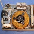 Voltage stabilizer circuit
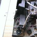 We extract radio components from various electronic trash How to make a radio receiver on a variable capacitor