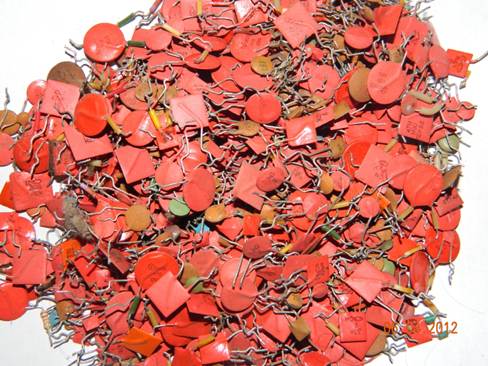
Radio elements from old equipment: capacitors. We get radio components from various electronic trash How to make a radio receiver on a variable capacitor
Recently, sorting through a bunch of rubbish at home, I found in parts a tube TV, two semi-disassembled imported receivers and one Soviet radio, as well as modules for the meter and decimeter range from a transistor television receiver. I didn’t want to throw it away, but on the other hand, I understood that I definitely didn’t need it in this form, so what should I do with this electronic rubbish? - that's right, throw it away ... but not all! Before throwing away from these boards, you can extract useful radio-electronic components for yourself, which will be convenient to store and can be useful later, if not to me, then to someone else as a gift.
Introduction
I’ll make a reservation right away: we won’t solder all the details, since most of them are already morally and physically obsolete, but we will extract only what can really be useful in the design of radio receivers, radio transmitters, transceivers and other home-made radio equipment.
Starting desoldering electronic trash, you need to understand that there are components that may lose their properties over time, such details include electrolytic capacitors.
Therefore, it’s not worth soldering electrolytes from old TVs and Soviet radios - this will save you nerves when designing devices and save you from failures, otherwise who knows what condition they are in - you can’t determine it with a simple dial-up tester.
Soldering a tube-transistor TV
Here is a photo of the main TV boards:
![]()
![]()
You can solder chocolate capacitors, low capacitance capacitors, high voltage capacitors and Mega Ohm resistors from the boards.
We also solder the diodes and you can remove the connectors - the sockets from them are suitable for old 2K2M type lamps and the like for 8 pins. Low-frequency transformers can be useful in the design of lamp equipment - we leave it to ourselves. Inductors with capacitors are hidden under aluminum screens, as well as printed circuit boards - radio frequency blocks.
![]()
As you can see, here you can profit from small capacitors, usually from 1 to 1000 picofarads, there are also diodes and chokes.
![]()
But in other modules there are inductors - of them frames with ferrite cores for tuning can be useful to us. We also solder capacitors and diodes from here.
![]()
The following radio modules are also interesting - in principle, everything can be soldered from them: transistor, thermistor (green ring), coils and chokes (blue), diodes.
![]()
Here's what I decided to leave out of the TV boards.
There are only three radios and there is something to profit from here:

The photo shows printed circuit boards from a Chinese-made music center-radio receiver.

But this printed circuit board is from some German radio, very high quality parts.


There are a lot of variable capacitors 5-20 pF, loop coils, as well as a 4-section KPI (variable capacitor) with a mechanism for dividing the number of revolutions of the handle.

Above are printed circuit boards from a Soviet-made Speedol radio receiver, and traces of modernization are visible on it - someone soldered GT322 transistors into the input circuits.

The most interesting thing from the Speedola receiver is the KPI (variable capacitance capacitor) with a vernier mechanism. Here it is two-section, each section is from 20 to 450 picoFarads.


From imported radios, I soldered almost all electrolytic capacitors, small capacitors, diodes and part of the resistors, all variable resistors, loop coils, a ferrite rod, variable capacitors (KPI), a microphone, chokes and transistors.
TV modules SKD and SKM

As I wrote at the beginning, there is also a reception module from a transistor-integrated TV - SKD-24-M.

This is what is inside such a block - a whole radio-electronic city from different components.

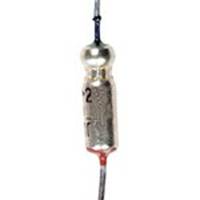
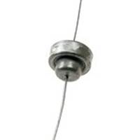
Guess what it is and the pins on which pieces of copper wire are wound? - from the signature below (C26) it is not difficult to understand that this is a capacitor, and this is a capacitor for several picofarads, its capacitance can be changed either by winding it up or by unwinding the turns, so you can adjust the desired circuit to the desired frequency or parameters. I have already met a similar solution and wrote about it in the article "Strela" tube radio receiver after half a century, I did not think that it was still used somewhere in more modern equipment.
Conclusion
So many useful electronic components can be extracted from non-working electronic equipment. Will they help me in the future? - time will tell, some parts have already come in handy for my single-tube regenerative radio.
These parts do not take up much space, it is convenient to store them after sorting them by type, and even better by denominations. For sorting, you can glue a cassette holder out of empty matchboxes - cheap and convenient.
The coolest DP ever!
Textbooks on radio engineering, of course, are necessary and useful to read. They just don't say it all. The nature of electromagnetic waves is much broader than our ideas. The ancestors of radio a hundred years ago understood this more clearly than we do. They followed NATURE, not TEXTBOOKS. The simplest designs worked wonders for them.
I, who am so cool, have read all the books and all the textbooks on detector receivers for a hundred years, both ours and foreign ones. Then, being proud of the acquired knowledge, I began to CREATE different models. It was possible to build a very short, but not bad antenna - three meters in height, fifteen - the horizontal part. (The capacitance of such an antenna is very significant). I've probably tried every possible scheme there is. The following facts have been experimentally revealed:
1) Receivers work perfectly, where there is no KPI at all, and the tuning is carried out with a variometer (see one of my posts) or a ferrovariometer. Either there is no capacitor, or a permanent conder is connected in series with the antenna.
2) A matching transformer at an audio frequency is power! The "background" of the air is listened to in 48-ohm monitor headphones (110 db/mV).
3) Diodes D9 - full g. D18 - this is cool !!! (Sometimes in "Chip and Dip. Sometimes") It's almost as cool as BAT85 (Schottky diode - always on sale). The latter, however, has a pronounced threshold, and does not hear weak stations, but it sounds great with a strong signal - high linearity and steepness of the CVC.
4) Litz wire, even domestic, on ferrite, drives. Q (When F meas \u003d 100 kHz) \u003d 110.
5) A coil wound on a cut of a fan pipe with an MGTF mounting (!!!) wire taxis doubly - the quality factor at a frequency of 100 kHz is already 120. For comparison, if it is wound enamelled, it will be somewhere around 50. Of course, this is a very indirect indicator, but I don't have a good Q - I don't have a meter. Oscilloscope too.
Somehow, in a fit of pride, I assembled a super-complex circuit with two circuits, a weak connection, a 4-diode bridge detector, and then set up this business from the GSS through the correct antenna equivalent. Everything is fine - a sensitivity of 1.5 millivolts. In practice, the 2 most powerful stations and both are quiet :(
Then I looked at the earliest detector receiver circuit - from Telefunken. 1905 I read Polyakov (you know what book I'm talking about). I thought again. I threw it out of the KPI scheme. I threw out from the circuit in general all unnecessary, in my opinion, details. The circuit took the form shown in Fig 1.
The receiver works perfectly - the restructuring is carried out by pushing the magnetic antenna into the coil (three stations at once), sufficient selectivity (we have Radio Russia and Slovo are very close, but they are tapped without overlaps).
How to explain all this - and hell knows, I'm not a theoretician. It must be assumed that the missing conder is successfully replaced by the capacitance of the antenna, as a result of which the “antenna-coil” system is tuned into resonance and acquires purely active resistance, as a result of which the current in the coil increases, and therefore the voltage on the detector increases.
In one of the models there was just an anecdotal case. It was a circuit with a coil, which had a hell of a lot of taps connected to the antenna through a switch. So, the wire leading to the KPI broke off from me. The receiver continued to work perfectly, and the stations were switched by taps :)
It has been experimentally found that the highest voltage on the detector in this configuration is provided if the load is 1 MΩ. As measured, I connected the GSS antenna through the equivalent, connected a variable resistor, and measured the resulting voltage with a high-resistance voltmeter (hundreds of megohm input). A matching transformer, measured at a frequency of 1 kHz, loaded with headphones, gives a resistance of about 70 kΩ, which, of course, is also not bad, but clearly not enough. We need to dig in that direction.
There was a question about improving the scheme. American colleagues in illness advise:
- Buy from them litz for 666 cores (to hell with it!) and don’t bathe with copper
- Wind a hefty (at least 14 cm in diameter) basket spool with it
- Get the 1N34A diode (I got it, but they all turned out to be burnt: (- no luck)
- Antenna resonance - I think correctly, the resonance should be left. This will be the 1st resonant circuit, which must be connected with the second c.-l. way.
- To tune out from local powerful stations, use a filter stopper (wavetrap).
- Well, and most importantly, to make the antenna bigger - to lift it on a kite or a balloon with helium. 3 meters is nonsense. At least 10, and even all 20!
I continue to slowly deal with the old military parts. This time - about coils and KPI, because for me this is a very "painful" issue.
Coils.
The circuits of the FC, of a rather rather large size, in a sealed sealed casing, with vitrified leads. Resistors and capacitors of the anode and grid circuits are installed inside. The amount of connection is regulated by a movable shutter, which changes the size of the gap in the partition. The date on the details is 1954. The build quality is impressive. Figured - the frequency is about 12 MHz.
The following IF circuits are no less interesting. Also soldered hermetically sealed copper case with vitrified leads. On the details - 1975. Most likely used in an AM receiver.
In the photo: the contours inside.
No less interesting contours of the inverter: a round case, for surface mounting. The screen is screwed onto the base; a groove is made in the base, into which a rubber seal is inserted. Inside the screen is a plastic insulating cup. I liked these circuits the most, because they are best suited for practical use in VHF receivers and there are enough of them for this.
In the photo: round contours of the inverter.
There are also a number of various coils on ribbed plastic and ceramic frames and on the frames of their plex. You can also apply in your designs:
In the photo: different coils.
And, finally, the most interesting "find" - a contour on a ceramic frame with a burnt silver coil. Never seen these before. I thought that such coils are only in textbooks, as an example of particularly stable circuits. It turns out that no, such exist in fact :) :) :) The design is also impeccable. But she has a size ... Well, she is completely unsuitable for VHF ...
In the photo: a burnt silver coil.
In addition, a colleague from St. Petersburg helped with the contours from an old TV, which I have been looking for for a very long time. They were used in TV sets "Friendship", "Wave", "Start", "Signal", which were produced in the late 50s and early 60s. These TVs themselves have already become a collector's item, so finding contours from them is a rarity. And they are good because the screen is removed without soldering (there are spring contacts on the base that are connected to the ground), the coil frame itself is screwed into the base, which allows you to rewind it without interfering with the installation in the basement of the chassis, and the leads are poured into the carbolite base, which allows you to make multiple soldering, again, without dismantling and without the risk of damaging the frame. In a word, simply wonderful contours!
In the photo: contours from TV.
Another St. Petersburg colleague donated 4 "double" circuits. They are good because they are designed for hanging installation. The frames are also carbolite and glued into the base. And the bad thing is that the threaded studs of the screen simultaneously press the base of the contour to the chassis. But somehow I'll try to apply them in the UPC.
I want to once again thank Alexander and Eduard for their help.
KPI
"Found" several interesting KPIs. This is, as it were, a block or something, consisting of two sections. Ceramic base, 5 mm thick, with a sleeve with a rolling bearing glued into it. A hollow axle is fixed in the bearing, on which two rotors are fixed. The stators are mounted on studs on both sides of the ceramic plate with a 180 degree offset. The capacitance of each section is approximately 5 ... 35 pF. Too much, but tolerable. Between the sections, above the plate, trimmers are installed. By design - just round plates, one of which is fixed, and the other is threaded. Just like a capacitor from a physics textbook! :):)
In the photo: KPE block.
These blocks are mounted on a ceramic axis with a diameter of 10 mm. Thus, it is possible to "assemble" KPI with the required number of sections.
Studying these blocks, I noticed that some of them have current collection on the rotor, and some do not. A question arose - how and why was KPI used without current collection from the rotor? But then I remembered that there are so-called. "KPE - butterfly". I just never met them. They have 2 stators and 2 rotors, moreover, the stators are isolated from each other, and the rotors are connected. Thus, energy is transferred from one stator to another through the rotors, i.e., in fact, these are 2 KPIs connected in series. The "classic" butterfly has 2 rotors on the same axis, spaced 180 degrees apart. Thus, the working angle of rotation is only 90 degrees. And this "butterfly" angle of rotation is 180 degrees. I measured the capacitance of the "butterfly" - it varies from about 4 to 18 pF, which is very suitable for a VHF unit.
Another "butterfly" was also found, but single and with a capacitance change range of 1.7 ... 5.7 pF, of a very similar design:
In the photo: single KPI - "butterfly"
Naturally, the "thought" immediately appeared to try to use these KPI blocks in their designs. The main difficulty is how to fix them. The simplest option turned out to be a printed circuit board, which I did.
In the photo: details of the future KPI from blocks with current collection on the rotor.
The stator leads are soldered to the tracks leading to the edge of the board. Conclusions of rotors - on "mass". I cut off the trimmers with a microdrill, since they are not needed in this case. Another difficulty of all KPIs of this type is the absence of a rotor rotation angle limiter. In the technique where they were used, this was solved by the vernier mechanism. Therefore, I came up with the simplest limiters from threaded racks.
In the photo: the design of the finished KPI and the stops-limiters from the racks.
I also had to shorten the ceramic axle, but it turned out to be so strong that it took a lot of work. Barely with a micro-drill with a fiberglass cutting disc, I made an incision around the perimeter and broke off the desired piece with effort.
I adjusted the board to the dimensions of the board of the "copper" VHF unit on the ECC2000. I experimented with varicaps on the second board of such a block (about a year ago) and decided to try the KPI on this board, because. it requires minimal labor costs :)
In general, I remade the board a little, made a screen for the contours and installed the KPI on the board. It turned out such a "shelf":
In the photo: a board with installed KPI.
Until the work was completed and, of course, did not turn on.
Well, the idea with the "butterfly" "hooked" me so much that for the last three weeks I have been working on this issue very closely. At first I just wanted to "try", but slowly it all "went" and grew into a full-fledged "project". But I'll talk about that another time :)
Again, there is a big break in the records ...
Okay, I'll try to remember what happened during this time.
Well, the fact that the work has not diminished is a fact. I'm sewing up...
I was on a business trip in Moscow. We went there by minibus, the journey took exactly 12 hours. From Vyshny Volochok and almost to Moscow itself - traffic jams. And I thought that this happens only in the city :) The work, which we planned to spend 5-6 days on, was done in 3 days - I really wanted to go home. :) They worked until 23...24 hours, there was nothing to do in the evenings anyway, so why waste time?
For the first time in the last, probably, 8-10 years, he sent a small parcel to Ukraine. It turned out that it was so difficult - all you need to do is fill out 2 customs papers. But expensive.
Visited Juno - haven't been there since October last year. Nothing has changed, the same assortment and all the same faces ... Actually, I was looking for probes with a hook-clamp or with a collet clamp, but I did not find it. But inexpensively bought with a friend two non-linear distortion meters "C6-5" and "C6-7" (by prior arrangement). In fact, they bought it because of the built-in millivoltmeter, and the cases will come in handy in the "household".
As an exchange-purchase, I received several parcels - with subminiature lamps (6Zh45B, 6X7B and 6S35B) and with a VHF unit from the Kazakhstan receiver, which until now was not in my "collection". True, it is "problematic" - the glass tube of the variometer is broken, but so far at least this. I was struck by its size - I did not think that it was so big.
In the photo: a general view of the VHF unit from above and below
In the photo: a general view of the inside and the board from the soldering side
In the photo: view of the board from the installation side and a broken tube with cores.
Schematic diagram of the VHF receiver "Kazakhstan".
So far, there are no plans for this block. I will slowly look for either a whole tube, or another similar VHF unit, and then we'll see.
Last summer, a colleague sent several KPIs from old military radio stations. When I ran into the problem of rebuilding the antenna circuit (see the previous message), I decided to try using them, because. they are three-piece. There are several types of KPIs. This particular one has three sections of approximately 4 ... 26 pF each (if my meter does not lie much) plus three 6 ... 10 pF trimmers, as well as ceramic finned coils mounted "in the basement" of the KPI, which I removed. Instead, I installed others, the same from some old equipment. Their base is made of ceramics, the coils themselves will be frameless, and a silver-plated brass core is inserted inside. Very similar to the KPV series trimmers:
In the photo: KPI top, bottom and coil frame.
The quality, as usual, is amazing: ceramic axle, rolling bearing, all plates are silver plated, and the stator and rotor are isolated from the body - do what you want! Of the shortcomings - there is no limiter for the rotation of the axis, you will have to "smart" something.
On the New Year before last, I was presented with a Baltika receiver (VEF factory, manufactured in 1950). Then, finally, I decided to see what happened to him. Appearance on the "four" - slightly "sharp", the scale peels off slightly, there is no nameplate "VEF" and small handles, the fabric is torn in one place. The back wall is in place and looks good. During disassembly, it turned out that there were no three rubber bands through which the chassis was attached to the case, the power cord was not native, the range switch lever was broken. A "crutch" was made on it - a bracket, but it did not work clearly and did not switch to all ranges.
He took out the chassis and speaker, cleaned it of dust and dirt and turned on the receiver. Loud hum from speakers. Inspected the installation - there are traces of a very sloppy repair. One of the terminals of the anode winding is cut off, and the kenotron rectifier is switched to the half-wave mode. I rang everything, restored it, turned it on again - the same strong hum. I measured the main voltage - everything is within normal limits. I used the old method - I took an electrolyte of 47.0 x 400 V and "tucked" it in parallel with the first electrolyte - the background immediately disappeared. I did not dismantle the "original" electrolyte, but simply mounted a new one in the basement. At the same time, I did the same with the second electrolyte.
In the photo: a general view of the basement of the chassis and the power cord assembly before rework.
I turned on the receiver, stuck the probe from the device as an antenna, on HF I even managed to "catch" something, on other bands - silence. I began to understand further - it turned out that almost all the coils of the MW and LW ranges are in a cliff - tails just stick out of the coils and braces from different places on the board. Who and why it took to do this - I'll never know. In general, a diagram, photos of this node from Kharchenko's website, long searches, cursing - and after a couple of hours we managed to unsolder everything into place. After that, I turned on the receiver - it works on all ranges. Yes, all the lamps (except for the kenotoron) are original, 1950, VEF-ovsky (there is a stamp on the end of the octal key), even with an "imported" designation. And workers!
In the photo: a view of the range switch assembly and the range switch lever.
What else struck me was the high sensitivity of the device. You just bring the probe from the multimeter to the socket, and it is already starting to accept something :)
The last thing I did was to slightly upgrade the "crutch" for the range selector lever. Now the switch works clearly and the "flag" of the range indicator works the same way.
Yes, I replaced 6E5 along the way - the original one was still a "matryoshka", but with a completely shrunken emission. "New" is also not quite new, but it still glows brightly enough. Yes, on the base of the "matryoshka" there is a risk indicator of the vertical position of the "eye". Later ones didn't do it...
After that, I collected everything in a case, tightened all the screws, and listened to the receiver a little. What can be said? It sounds good, but there are only a few stations on all bands. Yes, and the noise-crack of the ether is quite strong and unusual after VHF receivers. In general, the old man "cured", but what to do with him next - I'll never know :)
This weekend I made another attempt to tune two VHF units, which I had assembled quite a long time ago: on rod lamps (with inductive tuning) and on nuvistors (with KPI tuning). At the same time, I adjusted the UPCH unit on 1Zh18B rod lamps.
I started with the VHF unit on 1ZH29B.
VHF block on rod lamps.
The variometer mechanism had to be completely dismantled. I rewound both coils - I wound the local oscillator coil with a 1.5 mm silver-plated wire, the RF coil with an ordinary bare copper wire. The number of turns of both coils increased by one. Reduced the capacitance of the capacitor of the primary winding of the IF transformer - the setting has become more "sharp". I spent most of Saturday trying to set up this block. I changed the connection, squeezed and unclenched the turns, tried various combinations of the position of the variometer cores - all to no avail. 100 ... 108 MHz - no problem. You can shift the setting to the lower part of the range, but there the reception is much worse. Well, there is no way to stretch the setting over the entire range. In a word, he again abandoned this business until better times.
In the process of work, I tuned the UPCH on 1Zh18B lamps. I set it up more precisely, because. now I have a simple homemade 10.7 MHz oscillator.
UPC block on lamps 1Zh18B.
I have already described this block before. I tuned the contour of the fractional detector more precisely, selecting the capacitance of the secondary circuit by ear, with a minimum of distortion. It got better.
On Sunday, I took up the VHF unit on nuvistors.
VHF block on nuvistors.
I described this block in the same way earlier. I completely rewound the local oscillator circuit, increasing it by one turn, and reselected the tap points. Picked up the capacitance of some capacitors in the mixer and cascode. I made normal cores for contours. To do this, I removed the ferrite cores from the plastic threaded bushing and widened the hole in it. Then I cut the M3.5 thread on pieces of copper wire with a diameter of 3.7, dipped them in dichloroethane and screwed them into the bushings. It turned out pretty solid.
Further, using a receiver with a digital scale as a reference, I tried to lay down the limits of the range. Again, the main problem is with bottom part of the range. Through lengthy manipulations, I managed to achieve normal reception in the lower part, but the upper limit at the same time "rested" at 106 MHz. Those. now the receiver operates in the range of 87.5 ... 106 MHz. In addition, we managed to achieve uniform sensitivity over the entire range (this is still a problem!). Spent almost a whole day on this. On this I decided to stop for now and just listened to the radio all evening. Not bad, but not perfect, there is work to be done. Yes, the frequency stability is quite high - I listened to one of the stations for more than an hour, while the frequency did not go anywhere.
There are already certain ideas on how to try to stretch the scale to the entire range. I'll have to try, but it's probably next weekend. Actually, I'm quite happy with this block.
I made another design - a digital scale on the LC7265 + LB3500. It was too lazy to make it and not very interesting, but it can greatly facilitate the setup process. I assembled it, turned it on, some numbers appeared on the indicator, but when connected to the local oscillator, some kind of nonsense begins. So far put aside, but you need to bring to mind. I will describe in more detail later.
Where to get KPE?
I jumped a little in the "chronological" order.
In the spring, I was looking for a suitable KPI for a VHF tube unit. Could not find. If it cannot be found, then it must be made. "From scratch" is almost impossible without the appropriate equipment. And "on your knees" in the kitchen, you can only try to redo something. For alteration in the economy there was a two-section KPI 12 ... 495 pF. Such a capacitor was used in tube receivers of the 60-70s. It was released just in incredible quantities.
Remembering the previous not very successful alteration of the KPI from "Rigonda", I decided to slightly replenish my knowledge in this matter. Again he turned to the book: V.A. Volgov "Details and assemblies of radio-electronic equipment", pp. 155-202. There, perhaps, everything that is possible is written about KPI. Once again, I am amazed at how amazing this book is!
This table shows approximate KPI capacitance values for various ranges.
This table indicates the approximate number of plates in the KPI to obtain the desired capacity.
We remove the rotor - for this we unscrew the locking screw from behind. We "catch" the balls - there should be 8 of them.
The assembly-disassembly process will have to be repeated at least 4-5 times. We start with the rotor. We unsolder one section and with the help of wire cutters and microdrills we remove unnecessary plates.
Next, we put this section into "our" stator and assemble the KPI. Using paper pads, matches, toothpicks, we set the converted rotor to the desired position and solder it.
We disassemble the KPI again and do the same with the second section of the rotor.
We assemble the KPI again, after inserting the second rotor into our stator, we solder it.
Next, we disassemble the KPI, solder one stator - for this it is convenient to use suction. Remove unnecessary plates. We carefully clean the insulators from solder, install a converted stator on them and assemble the KPI. Initially, the stator is raised above the insulators by a few millimeters. When soldering, the stator must be installed directly on the insulators - this way we will slightly reduce the initial capacitance of the capacitor. We disassemble the KPI again and do the same with the second stator. We assemble and solder the second stator again.
For the last time, we disassemble the KPI, clean it from oxide, dirt, old grease. Next, we lubricate the bearing with a new TsIATIM-201 grease and assemble the KPI. After making sure that everything is fine, install the current collector plate.
In May, in the area of Sennaya Square, I discovered a commission store where they sell, among other things, old imported equipment. That's where I bought the tuner "Pioneer TX-530L". Transistor, somewhere in the early 80s, very inexpensive. I bought it only because of one detail - KPE.
Here is the second source where you can "get" KPI. Yes, this unit is the "younger brother" of what was later sent to me from Germany. The same Alps, but here there are two sections AM and three VHF.
Long suffered - to disassemble or not. After all, the tuner turned out to be working and I felt sorry. Later, I still soldered the KPE ...
They are polar and non-polar. Their differences are that some are used in DC voltage circuits, while others are used in AC circuits. It is possible to use fixed capacitors in AC voltage circuits when they are connected in series with the same poles, but they do not show the best parameters.
Capacitors non-polar
Non-polar, as well as resistors, are fixed, variable and tuning.
Trimmers capacitors are used to tune resonant circuits in transceiver equipment.
Rice. 1. PDA Capacitors
PDA type. They are silver-plated plates and a ceramic insulator. They have a capacity of several tens of picofarads. You can meet in any receivers, radios and television modulators. Trimmer capacitors are also denoted by the letters KT. This is followed by a number indicating the type of dielectric:
1 - vacuum; 2 - air; 3 - gas-filled; 4 - solid dielectric; 5 - liquid dielectric. For example, the designation KP2 means a variable capacitor with an air dielectric, and the designation KT4 means a tuning capacitor with a solid dielectric.
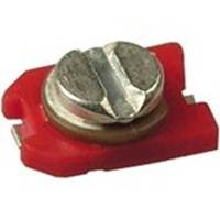
Rice. 2 Modern trimmer chip capacitors
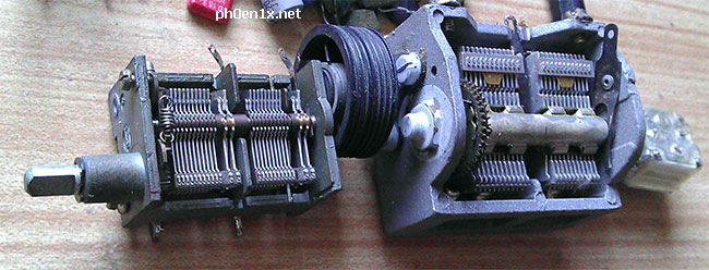
To tune radio receivers to the desired frequency, use variable capacitors(KPI)
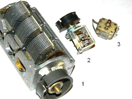
Rice. 3 Capacitors KPI
They can only be found in transceiver equipment.
1- KPI with an air dielectric, you can find it in any radio receiver of the 60-80s.
2 - variable capacitor for VHF units with vernier
3 - a variable capacitor, used in receiving equipment of the 90s to this day, can be found in any music center, tape recorder, cassette player with a receiver. Mainly made in China.
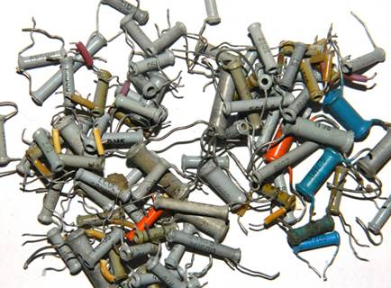
There are a great many types of permanent capacitors, within the framework of this article it is impossible to describe all their diversity, I will describe only those that are most often found in household equipment.

Rice. 4 Capacitor KSO
Capacitors KSO - Pressed mica condenser. Dielectric - mica, plates - aluminum sputtering. Encapsulated in brown compound. They are found in equipment of the 30-70s, the capacity does not exceed several tens of nanofarads, the case is indicated in picofarads, nanofarads and microfarads. Due to the use of mica as a dielectric, these capacitors are able to operate at high frequencies, as they have low losses and have a large leakage resistance of about 10^10 ohms.
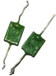
Rice. 5 Capacitors KTK
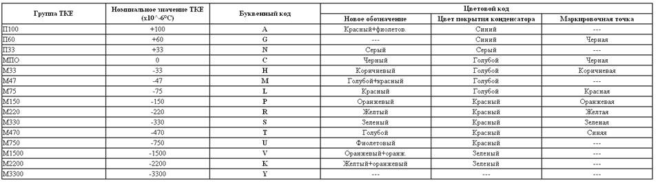
Capacitors KTK - Tubular Ceramic Capacitor As a dielectric, a ceramic tube is used, plates made of silver. They were widely used in the oscillatory circuits of lamp equipment from the 40s to the early eighties. The color of the capacitor means TKE (Temperature Coefficient of Capacitance Change). Next to the container, as a rule, the TKE group is prescribed, which has an alphabetic or numerical designation (Table 1.) As can be seen from the table, the most thermally stable are blue and gray. In general, this type is very good for HF technology.
Table 1. TKE marking of ceramic capacitors
When setting up receivers, it is often necessary to select capacitors for heterodyne and input circuits. If the receiver uses KTK capacitors, then the selection of the capacitance of the capacitors in these circuits can be simplified. To do this, several turns of PEL 0.3 wire are tightly wound on the capacitor case near the terminal, and one of the ends of this spiral is soldered to the terminal of the capacitors. By spreading and shifting the turns of the spiral, it is possible to adjust the capacitance of the capacitor within a small range. It may happen that by connecting the end of the spiral to one of the terminals of the capacitor, it is not possible to achieve a change in capacitance. In this case, the spiral should be soldered to another terminal.

Rice. 6 Ceramic capacitors. Soviet at the top, imported at the bottom.
Ceramic capacitors, they are usually called "red flags", and sometimes the name "clay" is also found. These capacitors are widely used in high frequency circuits. Usually these capacitors are not listed and are rarely used by amateurs, since capacitors of the same type can be made from different ceramics and have different characteristics. In ceramic capacitors, while gaining in size, they lose in thermal stability and linearity. The container and TKE are indicated on the case (table 2.)
table 2
Just look at the allowable capacitance change for capacitors with TKE H90, the capacitance can almost double! For many purposes, this is not acceptable, but still you should not reject this type, with a small temperature difference and not strict requirements, they can be used. Using the parallel connection of capacitors with different signs of TKE, one can obtain a sufficiently high stability of the resulting capacitance. You can meet them in any equipment, the Chinese are especially fond of in their crafts.
They have a capacitance designation in picofarads or nanofarads on the case, imported ones are marked with a numerical coding. The first two digits indicate the value of capacitance in picofarads (pF), the last - the number of zeros. When the capacitor has a capacitance of less than 10 pF, then the last digit can be "9". For capacitances less than 1.0 pF, the first digit is "0". The letter R is used as the decimal point. For example, code 010 is 1.0 pF, code 0R5 is 0.5 pF. A few examples are summarized in the table:
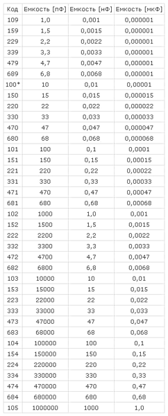
Alphanumeric marking:
22p-22 picofarad
2n2- 2.2 nanofarads
n10 - 100 picofarads
I would like to especially note ceramic capacitors of the KM type, they are used in industrial equipment and military devices, they have high stability, it is very difficult to find, because they contain rare earth metals, and if you find a board where this type of capacitor is used, then in 70% of cases they were cut out to you).
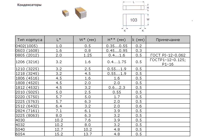
In the last decade, surface-mount radio components have become very often used, here are the main package sizes for ceramic chip capacitors
MBM capacitors - a metal-paper capacitor (Fig. 6.), As a rule, it was used in tube sound-amplifying equipment. Now highly prized by some audiophiles. Also of this type are capacitors K42U-2 of military acceptance, but they can sometimes be found in household appliances.
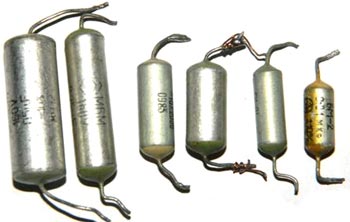
Rice. 7 Capacitor MBM and K42U-2
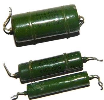
It should be noted separately such types of capacitors as MBGO and MBGCH (Fig. 8), amateurs are often used as starting capacitors to start electric motors. As an example, my margin for a 7kW motor (Figure 9.). Designed for high voltage from 160 to 1000V, which gives them many different applications in everyday life and industry. It should be remembered that for use in a home network, you need to take capacitors with an operating voltage of at least 350V. You can find such capacitors in old household washing machines, various devices with electric motors and in industrial installations. Often used as filters for acoustic systems, having good parameters for this.
Rice. 8. MBGO, MBGCH
Rice. 9
In addition to the designation indicating the design features (KSO - compressed mica capacitor, KTK - ceramic tubular, etc.), there is a designation system for constant capacitance capacitors, consisting of a number of elements: the letter K is in the first place, a two-digit number is in the second place, the first digit of which characterizes the type of dielectric, and the second - the features of the dielectric or operation, then the serial number of the development is put through a hyphen.
For example, the designation K73-17 means a film polyethylene terephthalate capacitor with the 17 serial number of development.

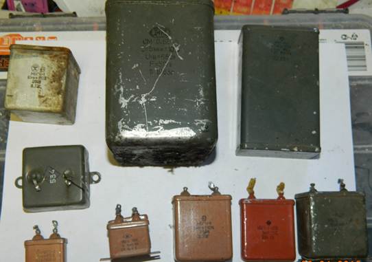
Rice. 10. Various types of capacitors
Rice. 11. Capacitor type K73-15
The main types of capacitors, imported analogues in brackets.
K10 - Ceramic, low voltage (Upa6<1600B)
K50 - Electrolytic, foil, aluminum
K15 - Ceramic, high voltage (Upa6>1600V)
K51 - Electrolytic, foil, tantalum, niobium, etc.
K20 - Quartz
K52 - Electrolytic, bulk-porous
K21 - Glass
K53 - Oxide-semiconductor
K22 - Glass-ceramic
K54 - Oxide-metal
K23 - glass enamel
K60- With air dielectric
K31- Low Power Mica (Mica)
K61 - Vacuum
K32 - High power mica
K71 - Film polystyrene (KS or FKS)
K40 - Paper low-voltage (Irab<2 kB) с фольговыми обкладками
K72 - Film fluoroplastic (TFT)
K73 - Film polyethylene terephthalate (KT, TFM, TFF or FKT)
K41 - High-voltage paper (Irab> 2 kV) with foil covers
K75 - Film combined
K76 - Lacquer film (MKL)
K42 - Paper with metallized plates (MP)
K77 - Film, Polycarbonate (KC, MKC or FKC)
K78 - Film polypropylene (KP, MKP or FKP)
Capacitors with a film dielectric are commonly called mica, various dielectrics used give good TKE performance. As plates in film capacitors, either aluminum foil or thin layers of aluminum or zinc deposited on a dielectric film are used. They have fairly stable parameters and are used for any purpose (not for all types). Found in household appliances everywhere. The case of such capacitors can be either metal or plastic and have a cylindrical or rectangular shape (Fig. 10.) Imported mica capacitors (Fig. 12)

Rice. 12. Imported mica capacitors
Capacitors are labeled with a nominal deviation from capacitance, which can be shown as a percentage or have a letter code. Basically, capacitors with a tolerance of H, M, J, K are widely used in household equipment. The letter indicating the tolerance is indicated after the value of the nominal capacitance of the capacitor, like this 22nK, 220nM, 470nJ.
Table for deciphering the conditional letter code of the permissible deviation of the capacitance of capacitors. Tolerance in %
|
Letter designation |
||
Important is the value of the allowable operating voltage of the capacitor, indicated after the nominal capacity and tolerance. It is indicated in volts with the letter B (old marking), and V (new marking). For example, like this: 250V, 400V, 1600V, 200V. In some cases, the letter V is omitted.
Sometimes Latin letter coding is used. For decoding, use the table of letter coding of the operating voltage of capacitors.
|
Rated voltage, V |
designation letter |
Fans of Nikola Tesla have a frequent need for high voltage capacitors, here are a few that can be found, mainly in line scanner televisions.

Rice. 13. High voltage capacitors
Capacitors are polar
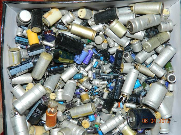
Polar capacitors include all electrolytic ones, which are:
Aluminum electrolytic capacitors have high capacitance, low cost and availability. Such capacitors are widely used in radio instrumentation, but have a significant drawback. Over time, the electrolyte inside the capacitor dries out and they lose capacity. Together with the capacitance, the equivalent series resistance increases and such capacitors no longer cope with the tasks. This usually causes malfunction of many household appliances. The use of used capacitors is not desirable, but still, if you want to use them, you need to carefully measure the capacitance and esr, so that later you don’t look for the cause of the device’s inoperability. I see no point in listing the types of aluminum capacitors, since there are no special differences in them, except for geometric parameters. Capacitors are radial (with leads from one end of the cylinder) and axial (with leads from opposite ends), there are capacitors with one lead, as the second, a case with a threaded tip is used (it is also a fastener), such capacitors can be found in the old tube radio and television technology. It is also worth noting that on computer motherboards, in switching power supplies, capacitors with low equivalent resistance, the so-called LOW ESR, are often found, and so they have improved parameters and are replaced only with similar ones, otherwise there will be an explosion the first time you turn it on.
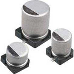
Rice. 14. Electrolytic capacitors. Bottom - for surface mounting.
Tantalum capacitors are better than aluminum capacitors due to the use of more expensive technology. They use a dry electrolyte, so they do not tend to "dry out" aluminum capacitors. In addition, tantalum capacitors have lower resistance at high frequencies (100 kHz), which is important when used in switching power supplies. The disadvantage of tantalum capacitors is the relatively large decrease in capacitance with increasing frequency and increased sensitivity to reverse polarity and overloads. Unfortunately, this type of capacitor is characterized by low capacitance values (usually no more than 100 microfarads). High voltage sensitivity forces developers to make the voltage margin Double or more.
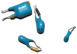
Rice. 14. Tantalum capacitors. The first three are domestic, the penultimate one is imported, the last one is imported for surface mounting.
Main dimensions of tantalum chip capacitors: 
One of the types of capacitors (in fact, they are semiconductors and have little in common with ordinary capacitors, but it still makes sense to mention them) includes varicaps. This is a special type of diode capacitor that changes its capacitance depending on the applied voltage. They are used as elements with electrically controlled capacitance in frequency tuning circuits of an oscillatory circuit, frequency division and multiplication, frequency modulation, controlled phase shifters, etc.


Rice. 15 Varicaps kv106b, kv102
Also very interesting are "supercapacitors" or ionistors. Although small in size, they have a colossal capacity and are often used to power memory chips, and sometimes they replace electrochemical batteries. Ionistors can also work in a buffer with batteries in order to protect them from sudden surges in load current: at low load current, the battery recharges the supercapacitor, and if the current rises sharply, the ionistor will release the stored energy, which will reduce the load on the battery. With this use case, it is placed either directly next to the battery, or inside its case. They can be found in laptops as a battery for CMOS.
The disadvantages include:
Specific energy is less than batteries (5-12 Wh/kg at 200 Wh/kg for lithium-ion batteries).
The voltage depends on the degree of charge.
Possibility of burnout of internal contacts in case of short circuit.
Large internal resistance compared to traditional capacitors (10 ... 100 Ohms for an ionistor 1 F × 5.5 V).
Significantly larger, compared with batteries, self-discharge: about 1 μA for an ionistor 2 F × 2.5 V.
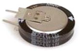


Rice. 16. Ionistors
Many people think passing by the market rows with Chinese products. Clocks that run for a month, kettles that boil for a week, hair dryers that blow for two hours.
All this is so. Nearly. But not really.
So, in order:
FIRST INSIDE IMPRESSION:
Cover fasteners, as a rule, with latches, plus a few screws, but if there are 4 or more screws, then there are no latches. For small cases, sometimes screws are not provided at all, sometimes there are 1 ... 2 pcs. Before opening the case, look carefully for these screws (for example, in the power compartment). They need to be unscrewed. Sometimes there is another screw opposite the telescopic antenna. He fastens it. This screw does not need to be removed.
The installation is such that the front and back are connected by wires. For operation, it doesn’t matter, but for tuning and repair, it’s a nasty little thing. In addition, the wires themselves are very economical. A plastic insulator of normal thickness (as MGShV 0.16 ... 0.25), and inside there are 3 ... 4 of the thinnest copper veins. When repairing these wires, they crumble like dust. They are usually soldered not where the Chinese designer came up with, but where the Chinese worker wanted. The designer cared about the nobility of the design, and the worker wanted to make fewer movements. As a result, the wires are not connected to specially dedicated printed pads, but nearby (it is already tinned there) or even to the other side of the board (it is really more convenient there). But during operation, all this has no role and does not play any significance. The second characteristic Chinese flaw is the randomly lying parts. Of course, the crooked part works fine, but the view is disgusting. The same conflict between the designer and the worker is to blame for everything. And the designer is 95% to blame here. Yet, although he is not a scoop, he lives in a socialist country. I think this is the reason. A good constructor (designer) will lay down in advance what the worker will do. Since electrolytic capacitors are lying around, it is necessary to immediately develop a board with parts laid on its side. I will also mention that the printed circuit boards are on getinaks (this is almost always in consumer goods), but the quality of both getinaks and boards is quite decent.
The speaker (dynamic direct-radiation head) with a nice shiny cap, but that's probably all that can be said about it. Sometimes (not often) fails due to a broken voice coil).
The KPI (Variable Capacitor - Provides frequency tuning) is perhaps the best part of these receivers. Four-section (two sections AM and two - VHF) with four trimmers. In general, a dream. Sometimes wax gets inside, which fixes the coils and then the KPI comes to an end.
The vernier is most often made as a plastic strip connected to the KPI tuning disk. Sometimes it is tightly attached to the KPI disk (it comes off if the receiver is roughly disassembled and glued back is difficult), sometimes it is separated along with a small plastic insert, sometimes it is a toothed strip (it works very reliably), but you have to tinker with the exact installation of the gear on the desired tooth, and sometimes a classic thread (this case is the angrier of all: if something breaks, you can fix it).
Range switches are not bad, but also suffer from wax.
The potentiometer (volume control) and the power switch, in my opinion, are rather frail by Russian standards. It can be twisted, loosened. Almost half of the defects are related to this part. The frail textolite cam of the switch also breaks, and the resistor itself can crack and the wheel fall off. Worse than this potentiometer are only potentiometers from Russia, although they are made according to the same Russian standards.
Resistors. Circuitry is such that there are almost none. And it is right. In practice, resistors appear only in different versions of ULF and volume control circuits.
Crystal IF filters: 10.7 MHz for VHF and 455 kHz for AM bands. Filters are common for modern equipment.
Screws, screws and self-tapping screws. There are not many of them and this is good, since they need to be screwed and tightly. As a rule, the case is screwed qualitatively. The remaining screws can dangle and unscrew (one of the characteristic defects is that the volume control wheel is poorly screwed.
Plastic. A good plastic molding in China. I like. The plastic is durable, hard, with a good texture. Sometimes the cases are made of painted plastic (the color is beautiful, mother-of-pearl, with a spark...). It's better not to take these. Very soon, the paint will begin to peel off and the appearance of the device will be the same. At elevated temperatures, thin plastic on the scale (both above and below the scale) behaves poorly. You might think there is no sun in China. Even in our latitudes, the scales are warped under the May sun like in a frying pan.
Setting. Let's just say none. It’s good that you don’t need to adjust the UPCH (piezo filters are everywhere). But where it is necessary to adjust, it is done poorly there. If the receiver does not catch well, then poor tuning is to blame in 90% of cases. The input circuit and the frequency discriminator circuit are two tuning kits. How to set up (or rebuild) .
A large receiver sometimes has a larger speaker. That's the whole difference between different models. Of course, in a large case, even a small speaker sounds better.
FIRST, EXTERNAL, IMPRESSION: a huge variety, but if the store has 100 varieties of cheese, then why not have 100 varieties of receivers. Appearance is cute, maybe a little Chinese voluptuous. How they love small decorations, roses, flowers. But we are already used to it, and not all models are like that. If we compare the external design of the CIS and PRC receivers, then there is nothing to talk about. A primitive appearance, uncomfortable regulators, some kind of ugly-looking plastic - all these are the prerogatives of Russian consumer goods.
COMPONENTS: almost all Korean or Japanese. Everything is close by and apparently very inexpensive.
Capacitors are ceramic and electrolytic. It would be better if they were smaller. The circuit is pretty clogged with electrolytic capacitors. There are more of them only in Russian receivers.
The contours are more or less unified and it pleases. For everything about everything, there are heels of the most popular coils, wound on ferrite spools and placed in a ferrite cup, which can be screwed up for tuning. There are three standard sizes of contours: small, even smaller and the smallest. The contours would be completely beyond criticism if it were not for the frail legs, which, when soldering, strive to start an independent life.
Transistors. The most common. In case of repair, they are replaced by KT3102 or KT3107 (depending on the type of conductivity).
Microcircuits. Korean or Japanese. Usually this is TA2003 (not to be confused with TDA2003) from TOCHIBA or CXA1191 (SONY) or its equivalent - KA22425 (SAMSUNG). The first of these three types of microcircuits does not contain ULF and receivers with this microcircuit shine with a variety of amplifiers from a transformer push-pull circuit to integrated ULF of various types. The CXA chip has an increased input sensitivity, especially on VHF, but often its input amplifier fails and then the receiver catches almost nothing at all; KA chip - has very uneven characteristics from copy to copy. Sometimes it catches great, sometimes so-so, and sometimes not at all. There is a suspicion that the cunning Chinese are buying rejected microcircuits at a low price. You can avoid trouble when buying by choosing the right receiver from several. (See below for how to choose.)
General circuitry has two options, since there are also two types of microcircuits. TA2003, in my opinion, catches and sounds a little worse, since it requires good ULF tuning (but tuning in China is as always tight), and this microcircuit was developed earlier than CXA1191 (late development is always better). The scheme is almost the same as recommended by the chip designer. The only difference is the replacement of the 10.7 MHz quartz in the frequency detector with a circuit with the same frequency. I don’t know what’s the matter, but I haven’t seen this quartz in any of the many hundreds of receivers (the developer recommends a quartz resonator (discriminator) of the CDA 10.7MG31 MURATA MFG.CO., LTD type).
General systems engineering., or rather its complete and brilliant absence. A dozen firms produce hundreds of models, and each model (may have several variants) is made as if there were no other receivers in nature. Besides outright blunders it is not clear why, for example, some receivers have a mono jack for headphones (headphones), while ordinary stereo phones have only one ear. The power socket (if there is: it seems difficult to put it everywhere) sometimes has + on the external contact (more often, although this is complete game), and sometimes on the internal one. Sometimes a small jack is used for power, sometimes a 3.5mm jack, and sometimes a 5.5mm jack. The most interesting thing is that even for one company, the larger the size of the receiver, the larger the size of the printed circuit board, although their circuits are absolutely identical. And on large boards there seems to be no empty space, and on small boards it is not very crowded. This riddle needs to be thought through. In all (almost) models, the power circuit is not fully developed. If you have an inexhaustible source of batteries, then everything is in order, but if you lead an economical lifestyle, then it would be better to use batteries. There is something to think about.
DEFECTS AND FAULTS
HOW TO CHOOSE:
 Do-it-yourself stabilizer - diagrams and recommendations on how to make a rectifier
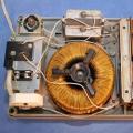 Voltage stabilizer circuit
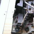 We get radio components from various electronic trash How to make a radio receiver on a variable capacitor