Voltage stabilizer 220v on transistors circuit. Do-it-yourself stabilizer - diagrams and recommendations on how to make a rectifier
The optimal way to operate electrical networks is to change the functions of the current, as well as the required voltage by 10% of 220V. However, since the surges change quite often, electrical devices that are directly connected to the network are in danger of breaking down.
To eliminate such troubles, it is necessary to install certain equipment. And since the store device has a fairly high cost, naturally, many assemble the stabilizer with their own hands.

Is such a decision justified and what is required to translate it into reality?

The principle of operation of the stabilizer
Having decided to create a homemade stabilizer, as in the photo, you need to look into the inside of the case, which consists of certain parts. The principle of operation of a conventional device is based directly on the operation of a rheostat, which increases or decreases resistance.


In addition, the proposed models have a variety of functions, and can also fully protect equipment from unwanted drops in the jumping voltage in the network.

Equipment is classified according to the methods used to regulate the current. Since the value is a directed movement of particles, it can be influenced accordingly by a mechanical or pulsed method.

The first works according to Ohm's law. Devices whose functioning is based on it are called linear. They include several knees, combined by means of a rheostat.

The voltage that is supplied to one part passes through a rheostat, turning out in a similar way to another, from which it is transmitted to the consumer.

This type of device makes it possible to set the required current parameters as accurately as possible and may well be upgraded with special units.

However, it is unacceptable to use such stabilizers in networks where the difference between the current is large, since they will not fully protect equipment from short circuits during overloads.

Pulse options operate according to the method of amplitude current modulation. The circuit uses a switch that breaks it after a required period of time. This approach makes it possible to accumulate the required current in the capacitor as evenly as possible, and at the end of charging and then to the devices.


Starting assembly
Since the triac device belongs to the most effective one, let's talk about how to make a similar stabilizer with your own hands.

It is important to emphasize that this type of model will be able to equalize the supplied current, provided that the voltage is in the range of 130-270 V. Components will also be required. Of the tools you need tweezers, as well as a soldering iron.

Production step by step
According to the detailed instructions on how to mount the stabilizer, first of all, you should prepare a printed circuit board of the required size. It is created from special foil fiberglass. The microcircuit of the arrangement of elements can be in a printed format, or transferred to the board by means of an iron.

Then, the scheme for creating a simple stabilizer provides for the assembly of the device itself. For this element you will need a magnetic circuit, several cables. One wire with a diameter of 0.064 mm is used to make the winding. The number of required turns reaches 8669.

The remaining two wires are used to create the remaining windings, which are characterized in comparison with the first option with a diameter of 0.185 mm. The number of equipped turns for these windings is at least 522.

If it is necessary to simplify the task, it is preferable to use series-connected transformers of the brand TPK-2-2 12V.

With independent production of these parts, at the end of the creation of one of them, they proceed to the production of another. For these purposes, a troidal magnetic circuit is required. PEV-2 with a number of turns of 455 is also suitable as a winding.


In addition, by step-by-step hand-made manufacture of the stabilizer in the second device, 7 taps should be made. At the same time, for several three, a wire of 3 mm in diameter is used, for others, tires of 18 mm2 with a cross section are used. This will make it possible to exclude unwanted heating of the device during the work process.

The rest of the items should be bought at a specialized outlet. Once everything you need is purchased, you should assemble the device.

Work should begin with the installation of the necessary microcircuit, which acts as a controller on an adjustable heat sink made of platinum. In addition, triacs are installed on it. Then flashing LEDs are mounted on the board.

If the creation of triac devices is a difficult task for you, then it is recommended to stop at the linear version, characterized by similar properties.

DIY photo stabilizers


The ideal option for the operation of power networks is to change the values of current and voltage, both downward and upward, by no more than 10% of the nominal 220 V. But since jumps are characterized by large changes in reality, electrical appliances connected directly to the network are in danger of losing their design capabilities and even failure.
Use of special equipment will help to avoid troubles. But since it has a very high price, many people prefer to assemble a do-it-yourself voltage stabilizer. How justified is such a step and what will be required for its implementation?
The design and principle of operation of the stabilizer
Instrument design
Having decided to assemble the device yourself, you will have to look inside the case of an industrial model. It consists of several main parts:
- transformer;
- Capacitors;
- Resistors;
- Cables for connecting elements and connecting the device.
The principle of operation of the simplest stabilizer is based on the operation of a rheostat. It raises or lowers the resistance depending on the current strength. More modern models have a wide range of functions and are able to fully protect household appliances from power surges.
Types of devices and their features

Types and their applications
The classification of equipment depends on the methods used to regulate the current. Since this value represents the directed motion of particles, it can be influenced by one of the following methods:
- mechanical;
- Impulse.
The first is based on Ohm's law. Devices whose work is based on it are called linear. They include two knees that are connected using a rheostat. The voltage applied to one element passes through the rheostat and thus appears on the other, from which it is supplied to consumers.
Devices of this type only allow you to set the output current parameters and can be upgraded with additional nodes. But it is impossible to use such stabilizers in networks where the difference between the input and output current is large, since they will not be able to protect household appliances from short circuits at high loads.
We watch the video, the principle of operation of a pulsed device:
Pulse models work on the principle of current amplitude modulation. The stabilizer circuit uses a switch that breaks it at regular intervals. This approach allows you to evenly accumulate current in the capacitor, and after it is fully charged, further to the devices.
Unlike linear stabilizers, pulse regulators do not have the ability to set a certain value. There are step-down models on sale - this is an ideal choice for the home.
Also, voltage stabilizers are divided into:
- Single-phase;
- Three-phase.
But since most household appliances operate from a single-phase network, in residential premises they usually use equipment belonging to the first type.
Let's start assembling: components, tools
Since the triac apparatus is considered the most effective, in our article we will consider how to independently assemble just such a model. It should be noted right away that this do-it-yourself voltage regulator will equalize the current, provided that the input voltage is in the range from 130 to 270V.
The permissible power of devices connected to such equipment cannot exceed 6 kW. In this case, the load switching will be carried out in 10 milliseconds.
As for the components, the following elements will be needed to assemble such a stabilizer:
- Power Supply;
- Rectifier for voltage amplitude measurement;
- Comparator;
- Controller;
- Amplifiers;
- LEDs;
- Load turn-on delay unit;
- autotransformer;
- Optocoupler keys;
- Safety switch.
Of the tools I will need a soldering iron and tweezers.
Manufacturing steps
To assemble a 220V voltage regulator for your home with your own hands, you first need to prepare a printed circuit board measuring 115x90 mm. It is made of foil fiberglass. The layout of parts can be printed on a laser printer and transferred to the board using an iron.
We watch the video, a home-made simple device:

circuit diagram
- magnetic circuit with a cross-sectional area of 1.87 cm²;
- three PEV-2 cables.
The first wire is used to create one winding, while its diameter is 0.064 mm. The number of turns should be 8669.
The two remaining wires will be required to complete the other windings. They differ from the first one with a diameter of 0.185 mm. The number of turns for these windings will be 522.
If you want to simplify your task, then you can use two ready-made transformers TPK-2-2 12V. They are connected in series.
In the case of manufacturing these parts on their own, after one of them is ready, they proceed to the creation of the second. It will need a toroidal magnetic circuit. For the winding, the same PEV-2 is chosen as in the first case, only the number of turns will be 455.
Also, in the second transformer, 7 taps will have to be made. Moreover, for the first three, a wire with a diameter of 3 mm is used, and for the rest - tires with a cross section of 18 mm². This will help to avoid heating the transformer during operation.

connection of two transformers
All other components for a do-it-yourself device are best purchased in a store. After everything you need is purchased, you can start assembling. It is best to start by installing a microcircuit that acts as a controller on a heat sink, which is made of aluminum platinum with an area of \u200b\u200bmore than 15 cm². Triacs are also mounted on it. Moreover, the heat sink on which they are supposed to be installed must have a cooling surface.
If assembling a 220V triac voltage regulator with your own hands seems difficult for you, then you can stop at a simpler linear model. It will have the same properties.
The effectiveness of a handmade product
What pushes a person to make a particular device? Most often - its high cost. And in this sense, a self-assembled voltage regulator, of course, surpasses the factory model.
The advantages of home-made devices include the possibility of self-repair. The person who assembled the stabilizer understood both its principle of operation and structure and therefore will be able to fix the malfunction without outside help.
In addition, all parts for such a device were pre-purchased in the store, so if they fail, you can always find a similar one.
If we compare the reliability of a stabilizer assembled by ourselves and produced at the enterprise, then here the advantage is on the side of the factory models. At home, it is almost impossible to develop a model with high performance, since there is no special measuring equipment.
Conclusion
There are various types of voltage stabilizers, and some of them are quite possible to do it yourself. But for this you will have to understand the nuances of the equipment, purchase the necessary components and perform their competent installation. If you are not confident in your abilities, then the best option is to purchase a factory-made device. Such a stabilizer is more expensive, but also significantly superior in quality to models assembled independently.
The mains voltage of consumers varies significantly due to line losses. The decrease in voltage can reach significant values and cause a malfunction in the operation of instruments and devices. Particularly affected by non-standard voltage are household appliances equipped with electric motors: refrigerators, washing machines, vacuum cleaners, water pumps and power tools.
The increased voltage of the mains leads to intense heating of the motor windings and wear of the collector, insulation breakdown. Reduced voltage does not have the best effect: electric motors do not start or turn on jerkily, which leads to premature wear of ballasts.
The way out of the created situation is quite simple - install a booster transformer, the total voltage of the secondary winding and the mains will become close to the standard supply voltage. Such a device does not have a negative effect on the power grid. The presence of a device for maintaining the mains voltage allows you to protect electrical appliances from both increased and reduced values.
In this device, a small power transformer is used to increase the voltage while maintaining the same power consumption. In a real device, it is enough to slightly increase the voltage of the mains with a voltage boost, and then stabilize it. The difference between the input and output voltage is used to compensate for undervoltage, the increased mains voltage is reduced by a transistor regulator.
Device characteristics:
Mains voltage 160-250 volts.
Secondary voltage 220 volts.
Load power up to 2000 watts.
Load current up to 5 Amperes.
Weight 2kg.
The price of the device mainly consists of the price of a power transformer of the TC180-TC320 type from old TVs and does not exceed 500 rubles. Transformers of the TN or CCI type with a secondary winding current of 6-8 Amperes have proven themselves well with a total voltage of the secondary windings of 24-36 Volts. The voltage stabilization device circuit consists of a power transformer T1, a powerful diode bridge VD1 of the power circuit and a key transistor VT1.
The error voltage tracking circuits consist of a diode bridge VD2 and an error amplifier on a parallel regulator DA1.
An increase in the voltage in the network leads to an increase in the voltage in the secondary winding of the 3T1 power transformer, the voltage across the capacitor C3 increases, which leads to the opening of the parallel regulator DA1 and shunting the voltage across the resistor R7. The voltage at the gate of the field-effect transistor VT1 drops and leads to its closing, which limits secondary voltage at terminals XT3, XT4.
The reduced voltage of the mains leads to the reverse process - a decrease in voltage on the secondary windings of the transformer, closing the parallel stabilizer at m / s DA1 and opening the field effect transistor VT1, which leads to an increase in voltage on the secondary windings.
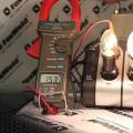
Adjusting the circuit consists in setting the limits for stabilizing the output voltage. After turning on (preferably to an active load in the form of a table lamp), resistor R5 sets the output voltage to 225 volts, connecting a more powerful load of 1-1.5 kW (in compliance with safety regulations) - correct within 220 volts.

After 5-10 minutes of operation, disconnect the device and the load from the mains, check the thermal conditions of all radio components, they should not be hot, otherwise increase the radiator of the key transistor.
Due to the gain spread of a powerful N-type field effect transistor, the initial offset can be corrected by selecting the resistance of the gate current resistor R4. Mount the transistor on a 50 * 50 * 20mm radiator through a mica gasket.
The printed wiring circuit and the transformer are installed in a suitable housing, the dimensions of which depend on the dimensions of the T1 transformer. The device operation indicator HL1 and the mains switch SA1 with fuses FU1, FU2 are located on the top and side of the case.
When using a metal case, use a power plug with a grounding knife, the output of which is connected to the case.
The radio components of the device are mostly factory-made, the transformer is used without alteration: the secondary winding 2T1 consists of two parallel windings of 36 volts, the third winding 3T1 with a voltage of 6.3 volts. Resistors such as MLT or C29. Trimmer type SP or SPO.
The power wires indicated in the diagram with thicker lines should be made with a stranded wire with a cross section of at least 4 mm., The remaining connections should be 0.5 mm.
List of radio elements
| Designation | A type | Denomination | Quantity | Note | Score | My notepad |
|---|---|---|---|---|---|---|
| DA1 | Reference IC | TL431 | 1 | To notepad | ||
| VT1 | MOSFET transistor | IRF840 | 1 | To notepad | ||
| VD1 | Diode bridge | RS805 | 1 | To notepad | ||
| VD2 | rectifier diode | RL102 | 4 | To notepad | ||
| VD3 | zener diode | KS156B | 1 | To notepad | ||
| C1 | Capacitor | 0.1uF 400V | 1 | To notepad | ||
| C2 | 10uF 450V | 1 | To notepad | |||
| C3 | electrolytic capacitor | 47uF 25V | 1 | To notepad | ||
| C3 | Capacitor | 1000 pF | 1 | To notepad | ||
| C4 | Capacitor | 0.22uF | 1 | To notepad | ||
| R1 | Resistor | 56 kOhm | 1 | 2 W | To notepad | |
| R2 | Resistor | 2.2 kOhm | 1 | To notepad | ||
| R3 | Resistor | 1.5 kOhm | 1 | To notepad | ||
| R4 | Resistor | 82 kOhm | 1 | 1 W | To notepad | |
| R5 | Variable resistor | 22 kOhm | 1 | To notepad | ||
| R6 | Resistor | 1 kOhm | 1 | To notepad | ||
| R7 | Resistor |
Household devices are sensitive to power surges, wear out faster, and malfunctions appear. In the electrical network, the voltage often changes, decreases, or increases. This is interconnected with the remoteness of the energy source and low-quality power lines.
To connect devices to a sustainable power supply, voltage stabilizers are used in residential premises. At its output, the voltage has stable properties. The stabilizer can be purchased at the distribution network, but such a device can be made by hand.
There are tolerances for voltage change no more than 10% of the nominal value (220 V). This deviation must be observed both upwards and downwards. But there is no ideal electrical network, and the voltage value in the network often changes, thereby aggravating the operation of devices connected to it.
Electrical appliances react negatively to such vagaries of the network and can quickly fail, while losing their inherent functions. To avoid such consequences, people use home-made devices called voltage stabilizers. An effective stabilizer was a device made on triacs. We will consider how to make a voltage stabilizer with our own hands.
Stabilizer characteristic
This stabilization device will not have increased sensitivity to changes in the voltage supplied through the common line. Voltage smoothing will be performed if the input voltage is in the range from 130 to 270 volts.
Devices connected to the network will be powered by a voltage ranging from 205 to 230 volts. From such a device it will be possible to power electrical devices, the total power of which is up to 6 kW. The stabilizer will switch the load of the consumer in 10 ms.
Stabilizer device
Scheme of the stabilization device.
The voltage stabilizer according to the specified scheme includes the following parts:
- The power supply unit, which includes capacities C2, C5, a comparator, a transformer, a thermoelectric diode.
- A node that delays the connection of the consumer's load, and consists of resistances, transistors, capacitance.
- Rectifier bridge measuring voltage amplitude. The rectifier consists of a capacitance, a diode, a zener diode, and several dividers.
- voltage comparator. Its components are resistances and comparators.
- Logic controller on microcircuits.
- Amplifiers, on VT4-12 transistors, current-limiting resistors.
- LEDs as indicators.
- Optitronic keys. Each of the nicknames is supplied with triacs and resistors, as well as opto-triacs.
- Electric machine or fuse.
- Autotransformer.
Operating principle
Let's see how it works.
After the power is connected, the capacitance C1 is in a state of discharge, the transistor VT1 is open, and VT2 is closed. VT3 transistor also remains closed. Through it, current is supplied to all LEDs and an optitron based on triacs.
Since this transistor is in the closed state, the LEDs do not light up, and each triac is closed, the load is turned off. At this moment, the current flows through the resistance R1 and comes to C1. Then the capacitor begins to charge.
The shutter speed range is three seconds. During this period, all transition processes are performed. After their completion, the Schmitt trigger is activated based on transistors VT1 and VT2. After that, the 3rd transistor opens and the load is connected.
The voltage coming from the 3rd winding T1 is equalized by the diode VD2 and capacitance C2. Next, the current flows to the divider on the resistances R13-14. From the resistance R14, a voltage, the magnitude of which is directly dependent on the magnitude of the voltage, is included in each non-inverting comparator input.
The number of comparators becomes 8. They are all made on DA2 and DA3 chips. At the same time, a direct current is supplied to the inverted input of the comparators, supplied with the help of dividers R15-23. Next comes the controller, which receives the input signal of each comparator.
Voltage stabilizer and its features
When the input voltage drops below 130 volts, a small logic level appears at the outputs of the comparators. At this moment, the VT4 transistor is open, the first LED is blinking. This indication indicates the presence of low voltage, which means that the adjustable stabilizer cannot perform its functions.
All triacs are closed and the load is off. When the voltage is in the range of 130-150 volts, then signals 1 and A have the properties of a logic high value. This level is low. In this case, the VT5 transistor opens, and the second LED starts to signal.
Optosimistor U1.2 opens in the same way as triac VS2. A load current will flow through the triac. Then the load will go into the upper output of the T2 autotransformer coil.
If the input voltage is 150 - 170 V, then signals 2, 1 and V have an increased logic level value. Other signals are low. With this input voltage, the transistor VT6 opens, the 3rd LED turns on. At this moment, the 2nd triac opens and the current flows to the second output of the T2 coil, which is the 2nd from the top.
A self-assembled voltage regulator for 220 volts will connect the windings of the 2nd transformer if the input voltage level reaches, respectively: 190, 210, 230, 250 volts. To make such a stabilizer, you need a 115 x 90 mm printed circuit board made of foil fiberglass.

The board image can be printed on the printer. Then, using an iron, this image is transferred to the board.
Manufacturing of transformers
You can make transformers T1 and T2 yourself. For T1, whose power is 3 kW, it is necessary to use a magnetic circuit with a cross section of 1.87 cm 2, and 3 wires of PEV - 2. The 1st wire with a diameter of 0.064 mm. They wind the first coil, with the number of turns 8669. The other 2 wires are used to form the remaining windings. The wires on them must be of the same diameter 0.185 mm, with the number of turns 522.
In order not to manufacture such transformers yourself, you can use ready-made versions of TPK - 2 - 2 x 12 V, connected in series.

To make a T2 transformer for 6 kW, a toroidal magnetic circuit is used. The winding is wound with PEV-2 wire with the number of turns 455. 7 taps must be brought out on the transformer. The first 3 of them are wound with 3 mm wire. The remaining 4 outlets are wound with tires with a cross section of 18 mm 2. With this wire section, the transformer will not heat up.
Branches are performed on such turns: 203, 232, 266, 305, 348 and 398. The turns are counted from the lower branch. In this case, the electric current of the network must flow through the outlet of the 266th turn.
Details and materials
The remaining elements and parts of the stabilizer for self-assembly are purchased from the distribution network. Let's list them:
- Triacs (optrons) MOS 3041 - 7 pcs.
- Triacs BTA 41 - 800 V - 7 pcs.
- KP 1158 EN 6A (DA1) stabilizer.
- Comparator LM 339 N (for DA2 and DA3) – 2 pcs.
- Diodes DF 005 M (for VD2 and VD1) - 2 pcs.
- Wirewound resistors SP 5 or SP 3 (for R13, R14 and R25) - 3 pcs.
- Resistors C2 - 23, with a tolerance of 1% - 7 pcs.
- Resistors of any rating with a tolerance of 5% - 30 pcs.
- Current-limiting resistors - 7 pcs, for passing a current of 16 milliamps (for R 41 - 47) - 7 pcs.
- Electrolytic capacitors - 4 pcs (for C5 - 1).
- Film capacitors (C4 - 8).
- Switch equipped with a fuse.
Optocouplers MOS 3041 are replaced by MOS 3061. KR 1158 EN 6A stabilizer can be changed to KP 1158 EN 6B. Comparator K 1401 CA 1 can be installed as an analogue of LM 339 N. Instead of diodes, KC 407 A can be used.
Chip KR 1158 EN 6A must be installed on the heat sink. For its manufacture, an aluminum plate of 15 cm 2 is used. It is also necessary to install triacs on it. For triacs, it is allowed to use a common heat sink. The surface area must exceed 1600 cm 2 . The stabilizer must be equipped with a KR 1554 LP 5 microcircuit, which acts as a microcontroller. Nine LEDs are arranged so that they fall into the holes on the front panel of the device.
If the device of the case does not allow them to be installed in the way as in the diagram, then they are placed on the other side, where the printed tracks are located. LEDs must be installed in a flashing type, but non-flashing diodes can also be mounted, provided that they glow with a bright red light. For such purposes, apply AL 307 KM or L 1543 SRC - E.
You can assemble simpler versions of devices, but they will have certain features.
Advantages and disadvantages, differences from factory models
If you list the advantages of self-made stabilizers, then the main advantage is low cost. Instrument manufacturers often inflate prices, and their own assembly will cost less anyway.
Another advantage can be determined by such a factor as the possibility of a simple do-it-yourself repair of a device. After all, who, if not you, knows better a device assembled by yourself.
In the event of a breakdown, the owner of the device will immediately find the defective element and replace it with a new one. The simple replacement of parts is created by such a factor that all parts were purchased in a store, so they can be easily bought again in any store.
The disadvantage of a self-assembled voltage stabilizer is to highlight its complex setting.
The simplest do-it-yourself voltage stabilizer
Consider how you can make your own 220 volt stabilizer with your own hands, with a few simple parts at hand. If the voltage in your electrical network is significantly reduced, then such a device will suit you just in time. To make it, you need a ready-made transformer, and a few simple parts. It is better to take such an example of a device as a note, as it turns out to be a good device with sufficient power, for example, for a microwave.
For refrigerators and various other household devices, a decrease in mains voltage is very harmful, more than an increase. If you raise the value of the mains voltage using an autotransformer, then during the decrease in the mains voltage at the output of the device, the voltage will be normal. And if the voltage in the network becomes normal, then at the output we will get an increased voltage value. For example, let's take a 24 V transformer. With a voltage of 190 V on the line, the output of the device will be 210 V, with a network value of 220 V, the output will be 244 V. This is quite acceptable and normal for the operation of household appliances.

For manufacturing, we need the main part - this is a simple transformer, but not electronic. You can find it ready-made, or change the data on an existing transformer, for example, from a broken TV. The transformer will be connected according to the autotransformer circuit. The output voltage will be approximately 11% higher than the mains voltage.
In this case, care must be taken, since during a significant voltage drop in the network upwards, the output of the device will receive a voltage that significantly exceeds the allowable value.
The autotransformer will add only 11% to the mains line voltage. This means that the power of the autotransformer is also taken at 11% of the power of the consumer. For example, the microwave power is 700 watts, so we take a transformer of 80 watts. But it is better to take power with a margin.
The SA1 regulator makes it possible, if necessary, to connect the load of the consumer without an autotransformer. Of course, this is not a full-fledged stabilizer, but on the other hand, its manufacture does not require large investments and a lot of time.
 Do-it-yourself stabilizer - diagrams and recommendations on how to make a rectifier
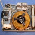 Voltage stabilizer circuit
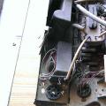 We get radio components from various electronic trash How to make a radio receiver on a variable capacitor