Electronic circuits for home circuit usb rs232. Null modem cable (RS232) wiring
Problems with the "firmware" of receivers. Lack of COM port. Laptop use
Most "old" computers and laptops purchased more than 5 years ago always had several COM ports (RS-232). At least there has always been at least one RS-232 connector.
Rice. 1. Connector on the computer case
Various external equipment was connected to it: mice, printers, modems, specialized equipment. Therefore, there were no problems with connecting the receiver to the computer for "firmware". It was enough just to connect, run the program to update the receiver's software and calmly do everything necessary.
In modern computers, the RS-232 connector is often absent. This is where problems arise, often very unpleasant. In most receivers, there is no other way of "flashing" other than using "RS-232". And not all receivers have a "USB" input for connecting an external flash drive.
And sometimes there is another problem: the laptop has a "COM" port, but it works with receivers of one model, but not with others. This is due to the violation by the laptop manufacturer of the "RS-232" data transmission standard. They go to this in order to save the energy of the battery charge. If the manufacturer of the receiver was technically scrupulous and accurate, then a special microcircuit for the "COM" port will be installed in the receiver. Thanks to this microcircuit, the receiver will work with both a laptop and a computer. But the installation of a microcircuit increases the total cost of the product, and lately, manufacturers are saving even on these trifles! Therefore, there is a problem of incompatibility between laptops and most receivers.
When using a computer, the problem of lack of the necessary "RS-232" ports is solved simply: you need to purchase an additional module with "COM" ports. This board installed in the computer is called "PIC-COM" or simply "COM port board".
Rice. 2. PCI card for a computer with two "COM" ports
If you are not good at computers and have never dealt with the installation of additional equipment in a computer before, then contact a specialist! Otherwise, you can "kill" expensive equipment.
After installing the card into the computer, the operating system "Windows" - "OS" assigns a number to the newly installed ports, for example, "1", "2" ... "25".
When using a laptop, you cannot install a regular board from a computer: it is not the same standard and size. There are two ways to solve this problem: expensive, but of high quality, and cheap, but not fully compatible. In the first case, you need to purchase a special board with ports for the laptop. The price for these boards is high, and I was not able to purchase this board, even on order.
Rice. 3. Board for laptop with "COM" port
And here's the catch: "old" and "new" laptops have two different standards for additional equipment! Before purchasing, check the instructions for your laptop!
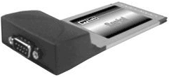
If you could not purchase a board for a computer or laptop, then there is only one way out: "USB". Almost all modern computer models have a "USB" output, at least two, or even all eight! Various USB to COM converters are available on the market.
Rice. 4. Converter "USB - COM"
Rice. 5. Scheme of the converter "USB - COM"
How to solder the USB-COM adapter yourself. Option 1
How to make a USB-COM adapter yourself, which can be used to connect converters and other devices to computers that do not have an "iron" COM port.
Attention!
The adapter described below will only match the RX and TX signals.
All other modem signals are inactive.
For most devices without hardware flow control, this is more than enough.
With Pilot VAF / MAF converters, the adapter works 100%
Go!
To assemble you need the following parts:
1. PL2303HX (USB-USART bridge from Prolific) -1pc.
2.MAX232CSE (UART-RS232) -1pc.
3. Quartz 12.00 MHz-1 pc.
4. Capacitors 10 nF (smd1206) -2 pcs.
5. Capacitors 1 uF (smd1206) - 6 pcs.
6. Resistors 27 Ohm (smd1206) -2 pcs.
7. Resistors 1.5KΩ (smd1206) -1pc.
8. Connector mini-USB -1 pc.
9. DB-9 male connector - 1 pc.
10. Foil PCB for board 48 * 22mm - 1pc
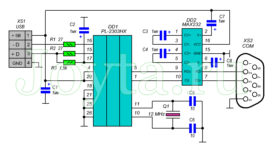
Adapter circuit

Printed circuit board

Schematic and print files in Eagle PCB Editor format can be downloaded (Downloads: 791)
Build and setup
Here, in fact, everything is elementary - we make a board, drill 4 holes and solder all the details.
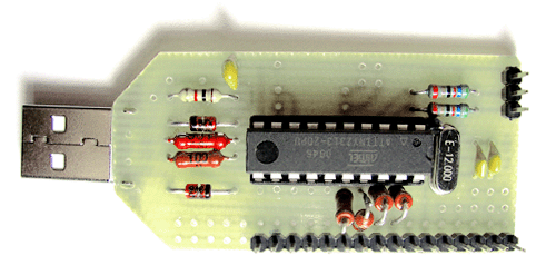
As a result, you should get such an adapter:

To prevent oxidation, the board can be blown out with polyurethane varnish or any quick-drying car varnish that is at hand.
Next, we connect this device to the USB port of the computer.
Windows will detect a new device and ask for a driver.
After feeding the driver to Windows, a new Prolific COM port should appear in the system:

Now you need to check the functionality of the adapter
To do this, on the adapter in the COM port connector, use a screwdriver or wire to close pins 2 and 3 together (on the connector itself, numbers with contact numbers are usually knocked out - take a closer look) Alternatively, you can solder a temporary jumper:

Run the program "Hyperterminal" (Start-> Programs-> Accessories-> Communication-> Hyperterminal)
There is no hyperterminal on whist and seven! Therefore, you will have to go to Google / Yandex to download the hyperterminal or any of its analogs.
We select our new som port in the connection settings:


Now we launch the connection, select the English layout and try to print something.
The symbols of the keys pressed should appear on the screen:

If the letters do not appear, then check the installation
That's all!
Now it remains to remove the jumper from contacts 2-3 and you can use the adapter for its intended purpose.
Those. the input of such a “converter” is connected to a free “USB” connector of the laptop, the driver (control program) is installed from the disk from the kit, and a virtual COM port with the assigned serial number appears in the system settings.
How to solder the USB-COM adapter yourself. Option - 2
Figure 1. General view

The proposed block in assembled form allows you to implement the principle: buy - connect. The device will allow users of personal computers to connect devices operating from the COM port (RS232C) to the USB port.
Estimated retail price: $ 18
The adapter will be useful in practical applications: for connecting various devices to a personal computer, as well as modems and programmers.
Specifications
Supply voltage from USB port: 5 V.
Consumption current: 20 mA.
RS232C communication speed: 110-230000 bps
Interface: USB1.1, USB2.0.
Supported operating systems: Win98, Win2000, WinXP, Vista, Linux, etc.
Overall dimensions of the device: 60x30 mm.
Contents of delivery
Adapter block assembly: 1.
Instructions: 1.
Design
Structurally, the adapter is made on a double-sided printed circuit board made of foil-clad fiberglass, protected by a transparent heat-shrinkable tube.
The adapter provides all modem signals: DSR, DTR, RTS, CTS, RI, DCD, as well as the main signals RXD and TXD.
Figure 2. Electrical schematic diagram
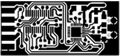
Figure 3. View of the printed circuit board from the side of parts
Block operation description
The schematic diagram is shown in Fig. 2.
The central part of the device is a CP2102 microcontroller manufactured by SILICON LABORATORIES. A MAX3243 converter manufactured by Texas Instruments is used as a level driver microcircuit. The adapter provides all modem signals: DSR, DTR, RTS, CTS, RI, DCD, as well as the main signals RXD and TXD.
Installing the device in the OS
To install drivers for your computer, you must first download the driver appropriate for your operating system.
Next, install the driver on your personal computer. Connect the adapter. The operating system will detect it and "ask" for the driver, you should tell it the location of this driver (the place where it was unpacked).
After successful installation, the LED on the adapter should light up, signaling the readiness of the device for operation!
Driver you can download (Downloads: 537)
PERFORMANCE CHECK BM8050 WITHOUT EXTERNAL EQUIPMENT
To check the transmission and reception of all necessary modem signals according to the connection of the COM device.

Place jumpers on pins 2-3, 4-6, 7-8 of the BM8050 COM-connector.
Connect the device to the USB port of the PC.
See which port the OS has allocated for the device, for which go to Start --- Settings --- Control Panel --- System --- Hardware --- Device Manager --- Ports (COM and LPT) --- Silicon Labs CP210x USB to UART Bridge (COM1).
Launch the standard HiperTerminal application for Windows from Start --- Programs --- Accessories --- Communication --- HiperTerminal.
Stop the running connection, if it is active, for which click the Call --- Stop above.
See which port is used by the program to communicate with the device, for which go to the top left File --- Properties and opposite "Connect via" select the same port as in the Device Manager (in our case, COM1).
In the same window, make sure that the "Hardware" flow control is selected in the program, for which click the button in the center "Configure" and in the lower "Flow control" window select "Hardware".
Exit the program settings, for which click OK, OK again.
Type the text "Text" in the HiperTerminal software, and the text "Text" is printed on the screen, which confirms that the device is working.
Remove the jumpers from contacts 2-3, 4-6, 7-8 of the BM8050 COM connector.

Type the text "Text" in the HiperTerminal software, and there is no print on the screen, which confirms that the device is working.
Driver setup and port selection for USB-COM adapter
Here the first problems await us: firstly, the OS could assign a too large number to the virtual port, for example, "25". And the program for "flashing" the receiver allows you to work with port numbers from one to four. Secondly, not all USB-COM converters can work with the firmware and the receiver itself. The reason is that equipment manufacturers have made their products and programs for them in different ways. It is necessary to check all converters individually for your program and your receiver. It often happens that the converter works with one piece of equipment, but not with the other.
If the first problem is fixed by changing the port number in the OS settings, then the problem of hardware, program and converter compatibility cannot be fixed.
To change the number assigned to the asset, you must change it manually. To do this, you need to enter the "Device Manager": "Start" - "Settings" - "Control Panel" - "System".

"Control Panel"
In the window that appears, select the "Hardware" tab and click on the "Device Manager" button. The Device Manager window opens. In the window that appears, in the tree-like list, select the line “Ports (COM and LPT). In the drop-down list, you will see all the ports available on your computer. Select your virtual port: "USB to COM converter". I have a "Prolific" model converter.
List of available ports
Click on this line with the RIGHT mouse button, in the window that opens, select the "Properties" construction.
Configuring the selected port
In the window that appears, select the "Port Settings" tab. In the line "Speed" select "115200", then click on the "Advanced" button.

Configuring Port Parameters
At the bottom of the window that opens, find the "COM port number" tab.
Changing the COM port number
Click on the tab and select the desired COM port number.
Note that some of the port numbers may be occupied by existing hardware, such as an internal modem. You cannot use one port at a time!
After completing the configuration, click "OK" to save the changes and completely exit the settings mode by closing all previously open windows. Then restart your computer to make the necessary changes. If you changed the “COM” number of the “USB-COM” port of the converter, then you just need to remove it from the computer connector and reconnect it.
Problems with the "firmware" of receivers. Lack of COM port. Laptop use
Most "old" computers and laptops purchased more than 5 years ago always had several COM ports (RS-232). At least there has always been at least one RS-232 connector.
Rice. 1. Connector on the computer case
Various external equipment was connected to it: mice, printers, modems, specialized equipment. Therefore, there were no problems with connecting the receiver to the computer for "firmware". It was enough just to connect, run the program to update the receiver's software and calmly do everything necessary.
In modern computers, the RS-232 connector is often absent. This is where problems arise, often very unpleasant. In most receivers, there is no other way of "flashing" other than using "RS-232". And not all receivers have a "USB" input for connecting an external flash drive.
And sometimes there is another problem: the laptop has a "COM" port, but it works with receivers of one model, but not with others. This is due to the violation by the laptop manufacturer of the "RS-232" data transmission standard. They go to this in order to save the energy of the battery charge. If the manufacturer of the receiver was technically scrupulous and accurate, then a special microcircuit for the "COM" port will be installed in the receiver. Thanks to this microcircuit, the receiver will work with both a laptop and a computer. But the installation of a microcircuit increases the total cost of the product, and lately, manufacturers are saving even on these trifles! Therefore, there is a problem of incompatibility between laptops and most receivers.
When using a computer, the problem of lack of the necessary "RS-232" ports is solved simply: you need to purchase an additional module with "COM" ports. This board installed in the computer is called "PIC-COM" or simply "COM port board".

Rice. 2. PCI card for a computer with two "COM" ports
If you are not good at computers and have never dealt with the installation of additional equipment in a computer before, then contact a specialist! Otherwise, you can "kill" expensive equipment.
After installing the card into the computer, the operating system "Windows" - "OS" assigns a number to the newly installed ports, for example, "1", "2" ... "25".
When using a laptop, you cannot install a regular board from a computer: it is not the same standard and size. There are two ways to solve this problem: expensive, but of high quality, and cheap, but not fully compatible. In the first case, you need to purchase a special board with ports for the laptop. The price of these boards is high, and I could not buy this board, even on order.

Rice. 3. Board for laptop with "COM" port
And here's the catch: "old" and "new" laptops have two different standards for additional equipment! Before purchasing, check the instructions for your laptop!
If you could not purchase a board for a computer or laptop, then there is only one way out: "USB". Almost all modern computer models have a "USB" output, at least two, or even all eight! Various USB to COM converters are available on the market.

Rice. 4. Converter "USB - COM"

Rice. 5. Scheme of the converter "USB - COM"
How to solder the USB-COM adapter yourself. Option 1
How to make a USB-COM adapter yourself, which can be used to connect converters and other devices to computers that do not have an "iron" COM port.
Attention!
The adapter described below will only match the RX and TX signals.
All other modem signals are inactive.
For most devices without hardware flow control, this is more than enough.
With Pilot VAF / MAF converters, the adapter works 100%
Go!
To assemble you need the following parts:
1. PL2303HX (USB-USART bridge from Prolific) -1pc.
2.MAX232CSE (UART-RS232) -1pc.
3. Quartz 12.00 MHz-1 pc.
4. Capacitors 10 nF (smd1206) -2 pcs.
5. Capacitors 1 uF (smd1206) -6 pcs.
6. Resistors 27 Ohm (smd1206) -2 pcs.
7. Resistors 1.5KΩ (smd1206) -1pc.
8. Connector mini-USB -1 pc.
9. DB-9 male connector - 1 pc.
10. Foil PCB for board 48 * 22mm - 1pc
Adapter circuit
Printed circuit board

Schematic files and seals in the format Eagle PCB Editor can be downloaded from this link
Build and setup
Here, in fact, everything is elementary - we make a board, drill 4 holes and solder all the details.
As a result, you should get such an adapter:

To prevent oxidation, the board can be blown out with polyurethane varnish or any quick-drying car varnish that is at hand.
Next, we connect this device to the USB port of the computer.
Windows will detect a new device and ask for a driver
We go to the site of prolific and download the latest version of firewood
At the time of this writing, the latest driver was this one.
After feeding the driver to Windows, a new Prolific COM port should appear in the system: 
Now you need to check the functionality of the adapter
To do this, on the adapter in the COM port connector, use a screwdriver or wire to close pins 2 and 3 together (on the connector itself, numbers with contact numbers are usually knocked out - take a closer look) Alternatively, you can solder a temporary jumper:
 Next, run the program "Hyperterminal" (Start-> Programs-> Accessories-> Communication-> Hyperterminal)
There is no hyperterminal on whist and seven! Therefore, you will have to go to Google / Yandex to download the hyperterminal or any of its analogs.
We select our new som port in the connection settings:


Now we launch the connection, select the English layout and try to print something.
The symbols of the keys pressed should appear on the screen:

If the letters do not appear, then check the installation
That's all!
Now it remains to remove the jumper from contacts 2-3 and you can use the adapter for its intended purpose.
Those. the input of such a “converter” is connected to a free “USB” connector of the laptop, the driver (control program) is installed from the disk from the kit, and a virtual COM port with the assigned serial number appears in the system settings.
How to solder the USB-COM adapter yourself. Option - 2
| Picture 1.General form |
 |
The proposed block in assembled form allows you to implement the principle: buy - connect. The device will allow users of personal computers to connect devices operating from the COM port (RS232C) to the USB port.
Estimated retail price: 540 rubles
The adapter will be useful in practical applications: for connecting various devices to a personal computer, as well as modems and programmers.
Specifications
Supply voltage from USB port: 5 V.
Consumption current: 20 mA.
RS232C communication speed: 110-230000 bps
Interface: USB1.1, USB2.0.
Supported operating systems: Win98, Win2000, WinXP, Vista, Linux, etc.
Overall dimensions of the device: 60x30 mm.
Contents of delivery
Adapter block assembly: 1.
Instructions: 1.
Design
Structurally, the adapter is made on a double-sided printed circuit board made of foil-clad fiberglass, protected by a transparent heat-shrinkable tube.
The adapter provides all modem signals: DSR, DTR, RTS, CTS, RI, DCD, as well as the main signals RXD and TXD.

Figure 2. Electrical schematic diagram
.gif)
Figure 3. View of the printed circuit board from the side of parts
Block operation description
The schematic diagram is shown on pic 2.
The central part of the device is a CP2102 microcontroller manufactured by SILICON LABORATORIES. A MAX3243 converter manufactured by Texas Instruments is used as a level driver microcircuit. The adapter provides all modem signals: DSR, DTR, RTS, CTS, RI, DCD, as well as the main signals RXD and TXD.
Installing the device in the OSTo install drivers for your computer, you must first download the driver appropriate for your operating system.
Next, install the driver on your personal computer. Connect the adapter. The operating system will detect it and "ask" for the driver, you should tell it the location of this driver (the place where it was unpacked).
After successful installation, the LED on the adapter should light up, signaling the readiness of the device for operation!
NEW Updated driver from 01/25/2011
1. Driver for Win Vista you can download
2. Driver for Windows 2000 / XP / Server 2003 / Vista (v5.0) You can download
3. Driver for Linux you can download
4. Driver for Win98SE you can download
5. Driver for OC Mac you can download
6. an144sw.zip- using this program, you can change the ID codes of the USB-COM adapter. This is necessary in order to be able to use several 8050s on one PC. Use for advanced users only! You can download
PERFORMANCE CHECK BM8050 WITHOUT EXTERNAL EQUIPMENT
To check the transmission and reception of all necessary modem signals according to the connection of the COM device.

Place jumpers on pins 2-3, 4-6, 7-8 of the BM8050 COM-connector.
Connect the device to the USB port of the PC.
See which port the OS has allocated for the device, for which go to Start --- Settings --- Control Panel --- System --- Hardware --- Device Manager --- Ports (COM and LPT) --- Silicon Labs CP210x USB to UART Bridge (COM1).
Launch the standard HiperTerminal application for Windows from Start --- Programs --- Accessories --- Communication --- HiperTerminal.
Stop the running connection, if it is active, for which click the Call --- Stop above.
See which port is used by the program to communicate with the device, for which go to the top left File --- Properties and opposite "Connect via" select the same port as in the Device Manager (in our case, COM1).
In the same window, make sure that the "Hardware" flow control is selected in the program, for which click the button in the center "Configure" and in the lower "Flow control" window select "Hardware".
Exit the program settings, for which click OK, OK again.
Type the text "Text" in the HiperTerminal software, and the text "Text" is printed on the screen, which confirms that the device is working.
Remove the jumpers from contacts 2-3, 4-6, 7-8 of the BM8050 COM connector.

Type the text "Text" in the HiperTerminal software, and there is no print on the screen, which confirms that the device is working.
Driver setup and port selection for USB-COM adapter
Here the first problems await us: firstly, the OS could assign a too large number to the virtual port, for example, "25". And the program for "flashing" the receiver allows you to work with port numbers from one to four. Secondly, not all USB-COM converters can work with the firmware and the receiver itself. The reason is that equipment manufacturers have made their products and programs for them in different ways. It is necessary to check all converters individually for your program and your receiver. It often happens that the converter works with one piece of equipment, but not with the other.
If the first problem is fixed by changing the port number in the OS settings, then the problem of hardware, program and converter compatibility cannot be fixed.
To change the number assigned to the asset, you must change it manually. To do this, you need to enter the "Device Manager": "Start" - "Settings" - "Control Panel" - "System".

Rice. 15.6. "Control Panel"
In the window that appears, select the "Hardware" tab and click on the "Device Manager" button. The Device Manager window opens. In the window that appears, in the tree-like list, select the line “Ports (COM and LPT). In the drop-down list, you will see all the ports available on your computer. Select your virtual port: "USB to COM converter". I have a "Prolific" model converter.

Rice. 15.7. List of available ports
Click on this line with the RIGHT mouse button, in the window that opens, select the "Properties" construction.

Rice. 15.8. Configuring the selected port
In the window that appears, select the "Port Settings" tab. In the line "Speed" select "115200", then click on the "Advanced" button.

Rice. 15.9. Configuring Port Parameters
At the bottom of the window that opens, find the "COM port number" tab.

Rice. 16. Changing the COM port number
Click on the tab and select the desired COM port number.
Note that some of the port numbers may be occupied by existing hardware, such as an internal modem. You cannot use one port at a time!
After completing the configuration, click "OK" to save the changes and completely exit the settings mode by closing all previously open windows. Then restart your computer to make the necessary changes. If you changed the “COM” number of the “USB-COM” port of the converter, then you just need to remove it from the computer connector and reconnect it.
Ready-made solutions for USB-COM adapters from manufacturers.
Adapter cable COM 9 / 25M -> USB AM 1m
Price - RUB 300
Description A cable for connecting devices with a serial interface (RS-232) to the USB port.
Cable or adapter connectors COM25M, COM9M, USB A
Compatibility
USB 1.1 / 2.0 compliant
Supports Windows 2000, Windows XP
Other
Cable length 1 meter
Logistics
Package dimensions (measured in NIKS) 21.5 x 14.5 x 4.1 cm
Gross weight (measured in NIKS) 0.136 kg
TRENDnet Adapter Cable 
Price - RUB 500
The main
Brand TRENDnet
Model TU-S9
Equipment type Adapter cable
Diameter 28/24 AWG
Performance parameters
Data transfer rate 500 Kbps
Powered by USB port
Power Consumption 500mA - Maximum
Compatibility
System Requirements RAM 64 MB
Supports Windows ME, Windows 2000, Windows XP
Other
RoHS Compliance
Cable length 0.6 meters
Weight 75 grams
Working temperature 0 ~ 40 ° C
Package dimensions (measured in NICS) 23 x 16.8 x 4.6 cm
Gross weight (measured in NIKS) 0.135 kg
External sources of information
Link to the manufacturer's website www.trendnet.com
Adapter - USB-COM (RS-232) adapter
Price - RUB 1,500
The adapter is intended for the use of devices and adapters designed to be switched on via the Com (RS232) port, for example, this is very important when using modern computers that have only USB, in this case, using this adapter, you can use modern computers and laptops together with our devices and adapters such as BMW Scanner, Mercedes Scanner, Scanmatik, etc.
Car service equipment, autodiagnostics, diagnostic equipment, auto diagnostics, car scanner, autoscanner, diagnostic post, chip tuning, car diagnostic equipment Carbrain, UNISCAN, ADP-504, KKL-USB, KKL-COM, BMW scanner, Opel scanner, BMW 1.3 .6, Automan, Opel scanner, BMW scanner, motor tester, gas analyzer, engine diagnostics, instrument panel diagnostics Transponder programmer, OBD-2, OBD2, odometer correction, U-581, engine start, crash data, crash date, crash date, speedometer, tachometer.
Although you may need to use a null modem cable (2-3, 3-2, 5-5) and an adapter of the type -

Add to the adapter USB extension cable here's a straight null modem cable.

- Retail value 100 rub.
- Type A-A
- Length: 1.5m
But for the rest you need " inverted" null modem cable.

- Retail price RUB 155.00
- Connector type: DB9 F - DB9 F
- Length: 1.8 m
or an adapter like this:
STLab U-350 (RTL) Adapter COM 9M -> USB AM
Price - RUB 350
The main
Manufacturer St-Lab
Model USB DONGLE SERIAL 1 PORT
Description The adapter allows you to connect a device with an RS-232 interface (for example, a modem) to a USB port on your computer.
Equipment type Adapter cable
Connectors for cable or adapter COM9M, USB A
Built-in USB connector Yes
Performance parameters
Baud rate 115200 bps
USB 1.1 interface
Powered by USB port
Supports Windows 2000, Windows ME, Windows XP, Windows Vista, Windows 2003 Server
Package dimensions (measured in NICS) 17 x 13 x 3.2 cm
Gross weight (measured in NIKS) 0.077 kg
External sources of information Link to the manufacturer's website
A COM USB adapter is a device that allows a personal computer to connect to various peripheral equipment. Unfortunately, modern models of system units do not sometimes have very important outputs. Thus, the user is limited in their capabilities.
If we consider such a device as a receiver, then it cannot be connected to the cable. In this case, the user can only be helped by the type of connectors, these devices differ. Additionally, it should be noted that it is quite possible to make them at home. However, first of all, it is important to familiarize yourself with their device.
Simple adapter circuit
The USB-COM adapter circuit includes a port, a modulator, a converter, and a resistor. In some cases, an additional amplifier may be located on the board. In this case, it is the wired models that are most often selected. Resistors in this case are used only of the open type. This is necessary in order to increase the maximum frequency of the device. Thus, the signal response time will be in the region of 20 ms. Among other things, consider the bandwidth of the device. To increase this parameter, many modulators advise using only double-sided ones.

Type A standard models
Making a type A USB-COM adapter with your own hands at home is quite simple. In this case, it is more expedient to select a microcircuit of the PP21 type. Only the converter will help to stabilize the process in the device. For normal operation of the model, a high-quality modulator is also required. For the specified microcircuit, it must be selected only of the low-frequency type. All this will allow the signal response parameter to be kept at around 30 ms.
For better current conductivity, experts also advise using low-power transistors. In this case, they must withstand the limiting voltage at a level of 3V. In general, these adapters are perfect for various types of receivers. Additionally, it is possible to connect radio receivers with SR101 connectors.
Type A mini models
Adapters of this type are capable of supporting many formats. It is impossible to fold them without converters. Additionally, you will need to select a PP22 series microcircuit. In total, there should be three transistors on it. In this case, two of them must be placed near the converter. In this case, it is important to select a modulator of a pulse type. The signal response speed is on average about 30 ms. This is quite enough for stable operation.
In this case, the cable must be attached to the back of the microcircuit. It is important not to touch the modulator during the soldering process. The transistors also need to be kept clean. The conjugation of the circuits is provided by a frequency amplification stage. On average, this parameter fluctuates around 12 Hz. To increase the conductivity of the current, some experts advise the use of amplifiers. The port for the device is connected last. The driver for the USB-COM adapter is selected separately.

Type A micro models
Making a type A micro USB-COM adapter with your own hands is quite difficult on your own. This is largely due to the presence of a non-standard port. The bandwidth for it must be quite high. In this case, the signal response parameter must be at least 20 ms. Separately, you should also pay attention to the search for the converter.
To increase the clock frequency in the device, many of them choose a symmetrical type. In this case, the transistors are selected in the open modification store. On average, they withstand voltage at the level of 3A. Alternatively, you can consider combined subspecies. All this will ultimately improve the speed of signal response.
How to make a standard type B adapter?
The presented USB-COM adapter cable is assembled for devices that have a connector of the RSR21 type. First of all, you need to select a modulator in the store. In this situation, you can stop at a stepped analogue. However, its bandwidth is rather low. Also, in the future, certain problems with overlapping contours may arise. To solve the presented problem, you can use oscillatory modulators.
They are quite expensive on the market, but testing of the devices shows that they are very good. First of all, they differ in the presence of copper contacts. Thus, their current conductivity is high. Among other things, it works quite well with a PP20 type microcircuit. In this case, the port must be installed last. In this case, the cable for it is selected separately.
Mini Type B Adapters
This COM USB adapter is assembled using a PP220 microcircuit. In this case, the converter must be selected with a chromatic resistor. Additionally, it is important to use only a high frequency modulator. To increase the speed of signal response, many experts advise the use of open-type transistors.
However, the devices will shrink significantly. As a result, there may be a problem with the installation of the device driver. Additionally, a trigger is mounted on the USB-COM adapter. This element in the system is responsible for the conjugation of the contours. This process takes place in the grid triode. In this case, the frequency gain increases significantly. The adapter port is selected without a selector.
Type B micro model
The adapters of the presented type are assembled quite simply. First of all, it should be noted that today they are quite popular. They are suitable for all devices on which there is a RSR 23 connector. Converters are selected for a pulse-type microcircuit only. In this case, it is best to use standard transistors. However, many specialists still prefer open-type analogs.
The bandwidth parameter in this case will depend on the type of amplifier. If you use a low-frequency modification, then problems with the device are inevitable. In turn, the longitudinal modifications significantly increase the current flow parameter. In this case, the cable is soldered to the convection output of the microcircuit.
How to choose a model in a store?
For devices with a RSR21 connector, select a high-frequency adapter. It must withstand the minimum load at a level of 3 A. The copper conductors must be necessarily oxygen-free. In this case, you can count on a good bandwidth of the device. The adapter must support "Dolby" and "True" digital formats.
In turn, the video system must work with 720p. Amplifiers in devices, as a rule, are installed contactless. However, some models have cheaper analog versions. The outer shell of the model must be made of PVC. The parameter of the signal response speed is on average in the region of 30 ms. A high-quality adapter will cost about 2500 rubles.
USB mini 4P specifications
The specified one differs from other devices in that it has a two-way modulator. Due to this, he has a pretty good one. For audio devices, the specified model is ideal. In this case, the traverse is set as an intermediate one. To stabilize the signal, a high-frequency amplifier is used in the device. The parameter of the response speed of the signal of the model is at the level of 25 ms. On average, the frequency of the device is located at around 23 Hz. To correct the current, the adapter has a small reflector.
USB model 1394B
Adapters of this type are capable of boasting a fairly high signal response speed. In this case, there is a low-frequency converter. In turn, the modulator is set with a cutoff frequency of 23 Hz. All this allows you to quickly stabilize the input voltage. Major formats are supported by installing a device driver. The amplifier in this case is of a pulse type. In turn, the high throughput was made possible by increasing the generation parameter.
The disadvantages of this adapter include a low overlap range. In this regard, conflicts often arise with the system when connecting peripheral devices. In addition, it should be borne in mind that the microcircuit of the model is installed in the PP19 series. Due to this, the parameter of the intermediate frequency never exceeds 30 Hz.

USB TDK device
This USB-COM adapter is most suitable for connecting receivers with a RSR30 connector to a personal computer. The transducer in this case is used with high sensitivity. In this case, the microcircuit is installed meridian. The modulator is connected to it with an operating frequency of 28 Hz. High bandwidth in the device is provided by high-quality transistors.
It should also be noted that the deviation at the transducer is quite rare. However, this adapter still has drawbacks. They are primarily associated with wave distortion. As a result, syncing the device can be time-consuming for the user.
USB-COM RS232
The USB-COM RS232 adapter is used to connect devices with RSR21 connectors. In this case, the high quality of the modulator deserves special attention. In this case, the microcircuit is used in a device of the PP21 type. The transistors of this model are installed of an analog type. They do not differ in special bandwidth. However, the parameter of the signal response speed of the presented adapter is at the level of 30 ms. This was largely achieved by installing a powerful converter.
It is able to maintain the operating frequency in the system at 23 Hz. Copper contacts are used in this case. All major formats are supported by the system. A driver for a USB-COM adapter can be purchased from the manufacturer. The outer shell of the device is made entirely of PVC. Additionally, it should be noted that the cut-off frequency parameter is exactly 30 Hz. In this regard, the bandwidth of the device is quite high.

USB MINI8M modification
This COM (USB port) adapter is suitable for devices with RSR26 series connector. In particular, these models are actively used to connect receivers to personal computers. Additionally, the modification can be installed in laptops. It is very compact in size. The outputs on the microcircuit are provided by the manufacturer of the coaxial type. In terms of sensitivity, this model does not differ from other devices. Additionally, it should be noted that the parameter of the operating frequency is at the damage of 21 Hz.
In this case, the conductivity of the resistors is not very high. As a result, the signal response speed is 20 ms on average. The model's intermediate frequency is 33 Hz. The modulators in this adapter are thermo-optical. Wave distortion occurs rather rarely in them. Additionally, it should be noted that the presented adapters often suffer from elevated temperatures. They can be used at a maximum of 40 degrees.

USB MINI8P parameters
This USB) adapter is most often installed under various receivers. The operating frequency is exactly 25 Hz. In this case, the signal response speed is at the level of 40 ms. The converter in this case is used by the manufacturer of the non-chromatic type. Its bandwidth is rather weak. However, it can withstand a load of about 3 A. Due to this, the stability of operation is ensured at a good level, and the transistors in the device rarely burn out. Among the shortcomings, it should be noted a sharp increase in the clock frequency. This is due to the out-of-sync of the modulator.

Devices with a connector on the controller
A USB-COM adapter with a connector on the controller is considered quite popular today. Various microcircuits can be selected for it. As a rule, low-frequency converters are installed. This is due to the fact that the signal response speed of the models is good. Modulators for this type of adapters are used only meridian. All this leads to an increase in the limiting frequency up to 30 Hz. However, the stability of the device can be controlled by installing an amplifier on the model.
Peripheral connector models
Adapters with a connector on a peripheral device are not very popular. First of all, they are absolutely not suitable for laptops. Additionally, their microcircuits can only be used in the PP13 series. All of this ultimately entails a number of problems. First of all, it should be noted the low parameter of the intermediate frequency at the level of 10 Hz. This is due to the lack of an input resistor on the board.
Also, problems with such models often arise due to a sharp drop in voltage. This happens when the load on the converter exceeds 3 A. However, despite all the above disadvantages, adapters with a connector on the peripheral device are still useful when it comes to connecting equipment with an RSR24 output.
This article provides a selection of circuits that allow you to assemble a simple, but extremely useful device: Com adapter.
Serial port (RS-232), or as it is also called COM-port, is designed to exchange information between a computer and peripheral devices. It was called sequential because the exchange of data on it occurs bit by bit one at a time.
Originally, the COM port was intended to connect the modem to a computer. In the future, they began to connect a mouse, a scanner, and other peripherals to it. It is also possible to organize a direct connection of two computers using a COM port.
Today, the vast majority of computers are not equipped with an RS-232 connector, since the USB standard has become widespread. But there are still many external devices working only with a COM port (various programmers, diagnostic equipment, receivers, etc.). The way out of this situation is to use a COM-USB adapter device. Below are several options for the most popular circuits of this adapter.
Complete adapter - COM adapter for USB port
on the FT8U232BM chip
The basis of this circuit is the FT8U232BM microcircuit - manufactured by FIDI Ltd. The device built according to this scheme supports all signal levels (DCD, RX, TX, DTR, GND, DSR, RTS, CTS, RI) according to the COM port pinout.

Operating voltage: 3.3 ... 5.5 V, interface: TX RX VCC GND ...

 To match the TTL levels of the RS232 interface with the levels of the FT8U232BM microcircuit, two 74HC00 microcircuits are used. The 93C46 memory chip is designed to store the personal number (PID), manufacturer's code (VID), as well as the serial number of the device. This microcircuit does not need to be installed. In this case, it will be possible to connect only 1 device creating a virtual COM port to the computer. The memory chip AT93C46 can be replaced with AT93C66, AT93C56. 93С46 is flashed directly on the board using the manufacturer's proprietary utility FTDI.
Simplified version on FT8U232BM
This is a diagram of a simplified USB-COM adapter that only supports signal lines RX, TX, RTS, CTS RS232 interface. To match com port levels with digital levels FT8U232BM added to the circuit.

Adapter circuit for COM from USB to PL2303
The following circuit is based on the PL2303HX chip, which is a USB to RS232 converter. PL2303HX is manufactured by Taiwan Prolific. This circuit also uses a MAX232 transceiver that converts the RX, TX signals.
For proper operation, you need to install the driver for the virtual COM port. To do this, download and install the driver from the link below.
Then we configure the virtual port: we set it in the "flow control" window - NO. Then we select a free port number.

USB - COM adapter on the Attiny2313 microcontroller
 Power is supplied directly from the USB power bus. The entire circuit is assembled on a single-sided board (SMD and TN options). The device only supports Rx and Tx signals.

The firmware for the adapter, the drawing of the printed circuit board (SMD and TH), as well as the terminal program for testing the adapter can be downloaded from the link below:
When, fuses must be set as follows:

For the device to work, you need to install the virtual COM port driver. To do this, download it:
Now we insert our adapter into the USB port of the computer, the computer should display the message "Found a new device", and then will offer to install a driver for it. Select the item "Install from a specified location" and click on the button "Next". Then, in a new window, select the path to the folder of the downloaded and unpacked driver and press the "Next" button again. After a few seconds, the driver will be installed and the device will be ready for use.
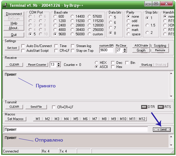
To check the operability of the device, temporarily close the Rx and Tx outputs and from the terminal program, which is also in the archive, set the COM port number and send any message. To do this, write for example "Hello" and press the "Send" button. If the adapter is working, then the written message will appear in the upper window of the program.
COM-USB adapter for Atmega8 microcontroller
Another COM-USB adapter circuit is now on the Atmega8 microcontroller (Atmega48, Atmega88). The circuit provides processing of Rx, Tx, DTR, RTS, CTS signals of the RS232 interface. The virtual port driver for this circuit is the same as for the attiny2313 adapter.

Firmware for atmega8 / 48/88 and PCB drawing can be downloaded from the following link:
Programming fuses for atmega8 / 48/88:

 Multichannel automated warning systems series "Rupor
 Null modem cable (RS232) wiring
 Configuring RIPv2 on Cisco Equipment