A simple electronic thermostat for the refrigerator on the LM35. Scheme and description
Simple refrigerator thermostat
DIYMake a Simple Refrigerator Thermostat Circuit
Want to make an accurate electronic thermostat for your refrigerator? The solid state thermostat circuit described in this article will surprise you with its "cool" performance.
Introduction
A device, once built and integrated with any suitable device, will instantly begin to exhibit improved system control, saving energy, as well as increasing the life of the device. Conventional refrigeration thermostats are expensive and not very accurate. Moreover, they are subject to wear and therefore are not permanent. A simple and efficient electronic refrigeration thermostat is discussed here.
A thermostat, as we all know, is a device that is able to perceive a certain set temperature level and turn off or switch an external load. Such devices may be electromechanical types or more complex electronic types.
Thermostats are usually associated with air conditioning, refrigeration and water heating devices. For such applications, the device becomes an important part of the system, without which the device can reach and start working in extreme conditions and eventually get damaged.
Adjusting the control switch provided in the above devices ensures that the thermostat turns off the power to the device after the temperature crosses the required limit and switches back as soon as the temperature returns to the lower threshold.
Thus, the temperature inside refrigerators or room temperature through the air conditioner is maintained in favorable ranges.
The refrigeration thermostat circuit idea presented here can be used externally above a refrigerator or any similar device to control its operation.
Controlling their operation can be done by attaching a thermostat sensing element to an external heat sink, usually located behind most refrigerant units that use freon.
The design is more flexible and wider than built-in thermostats and is able to show better efficiency. The circuit can easily replace conventional low-tech designs, and besides, it is much cheaper compared to them.
Let's understand how the circuit works:
Circuit Description
A simple refrigerator thermostat circuit
The diagram shows a simple circuit built around IC 741 which is basically configured as a voltage comparator. It uses a lower power transformer to make the circuit compact and solid state.
The bridge configuration containing R3, R2, P1 and NTC R1 at the input forms the main sensing elements of the circuit.
The inverting input of IC is clamped to half the supply voltage using the voltage divider network R3 and R4.
This eliminates the need to provide dual power to the IC and the circuit can provide optimal results even with a single supply voltage.
The reference voltage to the non-inverting input of IC is clamped across a given P1 with respect to NTC (Negative Temperature Coefficient).
In the event that the temperature under control tends to drift above the desired levels, the NTC resistance drops and the potential at the non-inverting input of IC crosses the set value.
This instantly switches the output of the IC, which in turn switches the output stage containing the transistor, the triax network, turning off the load (heating or cooling system) until the temperature reaches a lower threshold.
The feedback resistance R5 to some extent helps to induce hysteresis in the circuit, an important parameter without which the circuit can spin rapidly in response to sudden changes in temperature.
Once the assembly is completed, setting up the circuit is very simple and is done with the following points:
REMEMBER EXTERNAL CIRCUIT BASED ON CONSTANT SOURCE POTENTIAL, CAUTION WARNING IS WARNED TO AGAINST TESTING AND INSTALLATION PROCEDURES. THE USE OF A WOOD PLANK OR ANY OTHER INSULATING MATERIAL ON YOUR FOOT IS STRONGLY RECOMMENDED; ALSO USE ELECTRIC TOOLS WHICH SHOULD BE INSULATED NEAR THE SITE.
How to set up this electronic refrigeration circuit thermostat You will need a sample heat source finely adjusted to your desired cutoff threshold level for the thermostat circuit.
Turn on the circuit and enter and attach the above heat source to the NTC.
Now adjust the preset so that the output just switches (the output LED lights up). Remove the heat source from the NTC, depending on the hysteresis of the circuit, the output should turn off within a few seconds.
Repeat the procedure many times to confirm its correct functioning.
This completes the setup of this refrigeration thermostat and is ready to be integrated with any refrigerator or similar device for precise and constant regulation of its operation.
Parts list
R2 = Preset 10KR3,
R9=56ohm/1watt
C1 = 105 / 400V
C2 = 100uF / 25V
Z1 = 12V, 1W zener diode
* option via optocoupler, added switch and diode bridge to the power supply

How to create an automatic refrigerator temperature controller circuit
The idea for this circuit was suggested to me by one of the keen readers of this blog, Mr. Gustavo. I posted one similar circuit for an automatic refrigerator thermostat, however the circuit was designed to detect the higher temperature level available at the back of the refrigerator grill.
Introduction
Mr. Gustavo didn't quite get the idea and he asked me to design a refrigerator thermostat circuit that could sense cold temperatures inside the refrigerator rather than hot temperatures at the back of the refrigerator.
So with some effort I could find a real Fridge Temperature Controller CHAIN DIAGRAM, let's explore this idea with the following points:
How circuits function
The concept is not very new nor unique, it is the usual comparator concept that has been included here.
IC 741 has been rigged in standard comparator mode and also as a non-inverting amplifier circuit.
The NTC thermistor becomes the main sensing component and is specially responsible for cold temperature sensitivity.
NTC stands for Negative Temperature Coefficient, which means that the thermistor's resistance will increase as the temperature around it drops.
It should be noted that the NTC must be rated according to these specifications, otherwise the system will not function properly.
The preset P1 is used to set the trip point of the IC.
When the temperature inside the refrigerator falls below the threshold level, the thermistor resistance becomes high enough and reduces the voltage across the inverting pin below the non-inverting pin voltage level.
This instantly makes the IC output high, activating the relay and turning off the refrigerator compressor.
P1 should be set so that the output of the op-amp goes high at zero degrees Celsius.
The slight hysteresis introduced by the circuit comes as a boon, or rather a blessing in disguise, because it causes the circuit to not switch quickly at threshold levels, but only reacts after the temperature has risen about a couple of degrees above the shutdown level.
For example, suppose if the trigger level is set to zero, the IC will turn off the relay at that point, and the refrigerator compressor will also be turned off, the temperature inside the refrigerator will now start to rise, but the IC will not switch immediately, but maintains its position as long as the temperature will not rise to at least 3 degrees Celsius above zero. 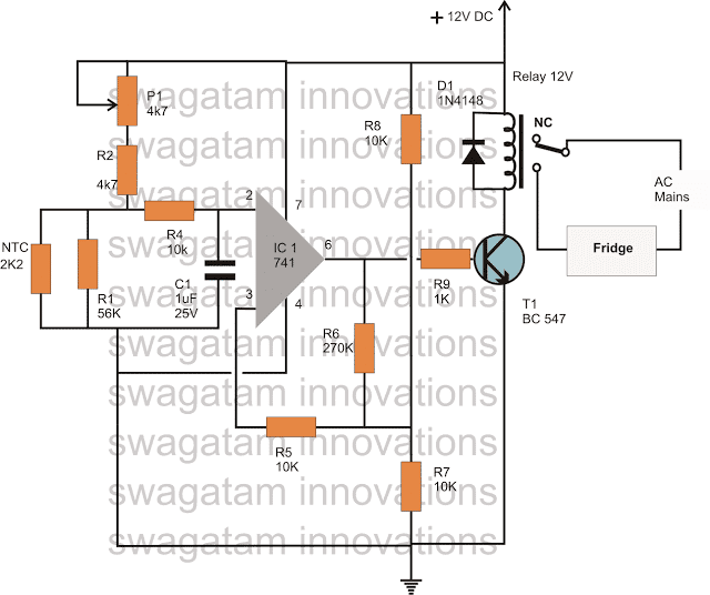
If you have further questions regarding this automatic refrigerator temperature controller circuit, you can express the same through your comments.
RP1, RP2 regulation can be set temperature control points, 555 time Schmitt circuit inversion circuit, using relays to achieve automatic control.

| Updated 01 Apr 2018. Created 29 Mar 2018 | |||||||||
To maintain the required temperature range in a modern refrigerator, a special thermostat device is used, abbreviated as a thermostat. The refrigerator thermostat switches the compressor on and off. Sometimes a situation arises when it fails, and there is nothing to replace it, then you can find the right solution and make it yourself, consider the diagram of such a device.
The thermostat has a galvanic isolation from the supply voltage and allows you to maintain the temperature inside the refrigerator chamber with a fairly good accuracy.

Refrigerator thermostat on OS TLC271
The temperature sensor is LM335. In fact, as follows from the description, this is a voltage regulator, the parameters of which are sensitive to temperature changes. The LM335 is connected with only two contacts. The cathode is connected to the plus through a load resistor R1, and the anode to the minus.
The voltage from the LM335 is fed to the direct input of the TLC271 comparator, at its inverse input there is a potential from the voltage divider across the resistances R3, R4, R5.
The temperature range in the internal chamber of the refrigerator is regulated by the variable resistance R4. If the temperature rises above this range, then the voltage at the direct input of the comparator will decrease compared to the inverse input. This will create a logic one signal at the output of the comparator, which will open the transistor.
Two optothyristors are connected in the collector circuit of the KT3102 transistor. Their LED parts are connected in series, while their thyristor parts are connected in parallel and in opposite directions. Therefore, an interesting opportunity appears to control alternating current (the first thyristor of the optocoupler operates on the first half-wave, and the second on the second half-wave. The refrigerator compressor turns on.
As soon as the temperature inside the refrigerator chamber drops below the set range, a logic zero level will form at the output of the comparator and the compressor will turn off.
With this version of the circuit, the compressor turns on when the temperature reaches + 6 degrees and turns off when it drops to + 4 degrees Celsius.
This temperature range is quite enough to maintain the required temperature for storing food, and at the same time, comfortable operation of the compressor is ensured, preventing its heavy wear. This is especially true in older models that use a thermal relay to start the engine.

Refrigerator thermostat on LM35
The thermostat reads the temperature with an LM35 sensor, whose resistance varies with the temperature in the refrigerator compartment, linearly calibrated with a factor of 10 mV per 1 degree Celsius.
Since the output voltage is clearly not enough to open VT1, the LM35 sensor is connected according to the current source circuit. Its output is loaded with resistance R1 and therefore the current strength varies in proportion to the temperature in the chamber. This current causes a drop across the resistance R2. The voltage drop controls the operation of the first bipolar transistor VT1. If the voltage drop is above the threshold voltage level of the emitter junction, both transistors open, relay K1 is activated, and its front contacts start the motor.
Resistance R3 creates a positive feedback loop. This provides a hysteresis to prevent the compressor from starting too often. The winding of the electromagnetic relay must be five volts, and its contacts must withstand the current and voltage flowing through them, see.
The LM35 temperature sensor is located inside the refrigeration unit in the correct location. The resistance of the resistor R1 is soldered directly to the sensor so that you can connect the LM35 to the board with just two wires.
If you need to slightly adjust the temperature level, then this can be done by selecting the resistance value of the resistors R1 or R2. Resistor R3 sets the amount of hysteresis.
The basis of the design is the K157UD1 operational amplifier with an output current of 300mA, which makes it possible to connect an optothyristor directly to the output of the op-amp without using a buffer transistor. The op-amp is included as a comparator. The refrigerator compressor shutdown temperature is set by the resistance R1. The difference between the on and off temperatures is set by the resistance R4.

Instead of an electronic key on an optotriac and a powerful triac VS1, you can use a conventional relay with a switching current of 10 Amperes. In this case, the relay winding is connected to the sixth pin of the DA1 chip and the third pin of DA2. A damping diode is connected to the same pins. In the case of using a relay, it will be necessary to increase the value of the capacitance of the capacitor C5 to 1 microfarad. If an electronic key is used in the design, then the diodes VD1 and VD2 can be eliminated by connecting the second output of DA2 directly to the case.

After all, no one can forbid us to use one of them for a possible replacement.
Do-it-yourself refrigerator thermostat
It all started with the fact that after returning from work and opening the refrigerator found it warm. Turning the thermostat knob did not help - the cold did not appear. Therefore, I decided not to buy a new unit, which is also rare, but to make an electronic thermostat on the ATtiny85 myself. With the original thermostat, the difference is that the temperature sensor is on the shelf, and not hidden in the wall. In addition, 2 LEDs appeared - they signal that the unit is on or the temperature is above the upper threshold.
Device Diagram:


To connect, it was necessary to conduct a second 220 V wire (taken from a lighting lamp) to power the transformer.
The connector to which the potentiometer is connected is also the ISP programming connector.

The board is protected from moisture with a special varnish for printed circuit boards.

The transformer here is 6 V. It was chosen to minimize losses on the 7805 chip.
The relay here can also be put on 12 V. If you take the voltage to it to the stabilizer. To reduce costs, it would be possible to create a transformerless power supply, although there are supporters and opponents of such a solution (electrical safety). Another cost cut is the elimination of the AVR microcontroller. There are Dallas thermometers that can also work in thermostat mode.
Let's start with the fact that the thermostat in the refrigerator serves to turn off / turn on the refrigeration compressor. When a working refrigerator is first turned on, the thermostat contacts are closed and a command is given to turn on the compressor. You can set the temperature in the refrigerator by turning the knob - the degree of cooling varies, as a rule, from +8 degrees to 0 degrees Celsius, a lower temperature is achieved by turning the thermostat knob clockwise until it stops.
To understand what malfunctions can be in the thermostat (thermostat) of the refrigerator, you need to understand its device.
Refrigerator thermostat device
The thermostat mechanism is a lever system that controls electrical contacts. Externally, the thermostat is a small box with a handle, on one side of which there is a tube filled with freon, and on the other side - contacts for connecting to an electrical circuit.


The number of contacts can vary from 2 to 6, and the length of the tube filled with freon can be from 0.8 to 2.5 meters. It depends on the additional functions of the thermostat, the temperature regime and the number of connected refrigerator modules (light, defrost, indication). It is not recommended to disassemble the working thermostat to study the internal structure.
![]()
![]()
Principle of operation
The principle of operation of the thermostat is quite simple. The end of the capillary tube of the thermostat is located in the cooling zone and is attached to the evaporator of the refrigerator. The lever mechanism of the thermostat, which is located in the box, acts on the contact group during cooling - the thermostat opens. When the temperature rises, the thermostat returns to its original position - the power contacts close.
Faults
Externally, the breakdown of the thermostat (temperature sensor) manifests itself in two ways. This may be a banal disconnection of the refrigerator compressor from the electrical circuit (the compressor does not turn on, there are no sounds, there is a light in the refrigerator), or it may change the temperature regime in the refrigerator compartment (freezing or high temperature).

In the first case, there is a high probability of damage to the galvanized capillary tube of the thermostat, which is subject to corrosion in the aquatic environment, as a result of which the lever mechanism of the thermostat simply stops working. In the second, it is necessary to understand what specifically caused the violation of the temperature regime - corrosion, sticking of the thermal relay contacts or a violation of the internal factory settings of the sensor. The answer can only be given by a specialist - a refrigerator repairman.
Installation location
A defective thermostat needs to be replaced. Replacing a broken thermostat yourself is quite simple if you get to the place of its installation. This is where the difficulties arise.
In modern refrigerators, the thermostat adjustment is usually displayed on the front panel and is located at the top of the refrigerator, but can also be located inside. The cooling module of the refrigerator (evaporator) is hidden under the plastic casing and is located at the rear.
To install a new thermostat yourself, you need to dismantle the broken thermostat.
- To do this, turn off the power to the refrigerator by pulling the cord from the mains.
- Depending on the model of the refrigerator, remove the plastic cover of the case, in which the broken thermostat is located.
- Mark the wiring diagram with a marker.
- Remove the capillary tube of the broken thermostat from the place of attachment (placement).
Install new thermostat in reverse order.
Connection Features
Do not confuse different thermostats that look similar to each other. Some can only work at positive temperatures, others are designed only for freezers. The use of a thermostat that is not designed to operate a refrigerator (freezer) can lead to incorrect operation of the equipment and failure of expensive elements (compressor).
Therefore, be sure to check the wires connected to the thermostat. It's one thing if you find your own replacement thermostat, of the same manufacturer or brand, and another if you use an analogue.

By the way, the wires suitable for the thermostat have the following purpose:
- orange, red or black - connects the thermostat to the compressor;
- brown - phase wire leading to the outlet;
- white, yellow or green - leads to a light indicating that the refrigerator is on;
- striped yellow-green - grounding.
Starting from the size of the contacts, location, temperature controllers can differ in the settings of the contact groups (power or low-current) and purpose (medium temperature or freezing). For example, the use of an outwardly similar temperature sensor K57-2.5 instead of K59-2.5 will lead to frosting in the rear wall of the refrigerating chamber and a change in the temperature regime of the refrigerator.
The refrigerator contains more often two thermal relays (thermostat), they are arranged differently, the functions are not the same. The first monitors the superheat of the compressor, the second - the temperature of the evaporator. Why are relays used? Simple, reliable. Today we see mechanical, electrical varieties. The thermal relay for the refrigerator acts as a bell that triggers a complex mechanism. The signal will not sound, the system will remain dead, forget the frost!
Where to look for a refrigerator thermostat
The owners of refrigerators with mechanical regulators took the thermostat by hand. Not everyone guessed. The handle that sets the temperature, the mode switch, is mounted on the rotary mechanism of the thermostat. It is formed by two main parts, thanks to which it is difficult to confuse the component:
- A box containing executive, control mechanisms.
- Long thin capillary (metal tube with an inner diameter of 0.5 mm).
Inside the box in a sealed casing is a bellows. A cylindrical metal accordion that monitors changes in ambient pressure by changing linear dimensions. To better visualize the shape, imagine a small length of corrugated metal hose. The difference between the measuring bellows: sealed at both ends, therefore, hermetic. When the pressure from the outside increases, the sensing element shrinks. The design contains a spring that changes the response of the bellows to the applied pressure.
To better understand the purpose, we will make a brief excursion into the production processes. Bellows are considered measuring elements of refrigerators. The element has many uses. In pipelines, the bellows serves as a damping element. The ambient temperature rises, the oil pumping line begins to expand in length. The rupture is a fire hazard. Bent the line with an arc. The bellows segment comes to the rescue. The accordion shrinks, nothing special happens to the pipeline when the temperature rises. The situation repeats itself, sensing frost.
Giant bellows (units of meters in diameter) are made of high quality steel. First, a cylindrical segment is drawn. Interesting things happen next. The cylinder is inserted into a special machine of impressive size, the press, equipped with a grip, squeezes the accordion several times, straightens it with a verified force. The platform rises, the podium exposes the bellows, which does not have pronounced elastic properties, like a spring. You can stretch, compress, as the press did, deform.

refrigerator thermostat
In order to balance the external pressure force applied to the bellows, gas is pumped inward for use in measuring technology. External, external influences are considered factors that lengthen, compress the bellows. Obviously, a thermal relay equipped with a sensitive element will operate at the same temperature. Refrigerators are also used in simple models. But it is much more convenient to see a device with a regulator that changes the response threshold, making the temperature in the refrigerator chambers correspond to the program.
A spring appears on the scene. The spiral covers the bellows, is attached to both soldered ends. The spring preload determines the response threshold of the sensing element. Some bellows are provided with one fixed actuation torque, others are designed to provide two ranges (chambers). It is clear that different models are used for the freezer and refrigerator compartments.
Refrigerator thermostat operation
We considered in detail the principle of operation of the bellows for a reason. Despite the dominance of electronics, thermal relays continue to be equipped with a proven element. There is no need to install low voltage power supplies.
Repair of the Stinol refrigerator thermostat has to be done approximately 5 years after the purchase of the equipment. This is the resource of a sensitive element produced by one German company.
Durability is doubtful, perhaps the matter is determined by accuracy, reliability. We believe the answer concerns the area of unification. The refrigerator works by forming four phase states of freon:
- Compression;
- Condensation;
- Extension;
- Evaporation.
Helps to get low temperatures. The refrigerator thermostat device provides for the use of freon. Why? Since freon becomes a gas inside the evaporator of the cooling circuit, it will easily change the state of aggregation inside the capillary tube of the thermal switch, which, as mentioned, is formed by two components (see above). We waited to indicate that the system is filled with refrigerant, completely sealed. The tube is sealed from the free end, there is freon under pressure inside, which allows it to become liquid, only the temperature of the evaporator drops below the threshold. Causes a shock pressure drop in the system, the bellows straightens.

The necessary contacts are closed, the control voltage of the compressor engine start relay is removed. As a result, the refrigerator stops, the temperature stops dropping. The state is saved until the threshold for switching on the thermal relay is passed. The freon inside becomes steam, the pressure on the bellows rises, the corrugation shrinks, the contacts of the control winding of the compressor engine start device close. The refrigerator turns on, works until the set parameters are reached.
Now a couple of remarks about the operation of the thermal relay. As mentioned above, the temperature of the evaporator is measured. How does this happen? We are amazed at the length of the sensitive tube. Incredible length, if necessary, reaches the floor. Is all freon involved in the process? The change in the state of aggregation occurs at the very tip with the capture of a relatively small area directly adjacent to the evaporator. Provides reliable contact. Glue is usually used, sealed with sealant on top. Excess turns of the sealed tube are placed in the space between the walls. A new refrigerator thermostat is being installed to replace the broken one.
Replacing a thermostat for a refrigerator is within the power of most craftsmen, a nuance has been noticed. The new thermostat for the refrigerator is similar to the old type. Otherwise, the result is very different from the expected. Separate thermostats for refrigerators provide the possibility of adjustment. Experienced craftsmen manage to solve the situation with honor. The breakdown of the thermal relay is often indicated by the fact: the temperature of the refrigerator does not closely correspond to the set one. Having turned the regulator knob to the Off position, we wait in vain to hear a characteristic click emitted by a working thermal relay. However, the factor is uncharacteristic of the fully electronic devices discussed below.

The control knob, which we turn and flip to adjust the temperature, directly acts on the refrigerator thermostat spring. The disadvantage of mechanical bellows is the difficulty in providing fine adjustment. Setting the modes is done in steps. For example, domestic thermal relays for TAM brand refrigerators support one or two modes. Caused by the difficulties of adjusting the spring.
Electronic thermal relays
They mentioned the difficulty of setting up bellows thermostats for refrigerators. Old proven developments have served more than one generation quite well. The electronic thermostat of refrigerators will allow you to flexibly monitor the behavior of the structure, provides ample opportunities for adjusting modes.
The sensitive element is a special resistor, a thyristor. The keys are formed by power transistors, it is possible to use ordinary relays. The disadvantage of electronic thermostats for refrigerators is limited by exorbitant energy consumption, however, we believe that durability is much more important.
Convenient electronic thermostats in refrigerators equipped with linear (piston) compressors. This is not a separate type of engine, rather a way of control. The pursuit of secondary parameters of refrigerators has been going on for a long time:
- Energy consumption.
- Noise level.
- Dimensions.
New models began to be equipped with inverter compressors at first, then linear compressors were introduced. They work without interruption, maintaining the temperature at a given level. Theoretically, we leave the mode noisy, in practice it turns out: the compressor works half-heartedly, it behaves incomparably quieter.
The adjustment of the thermostat in the refrigerator is fine, the sensor is sensitive so that the linear compressor works. Electronics provides such opportunities.
The refrigerator compressor thermostat will be discussed later.
 "Notification Center": what is it, how to disable the service How to disable system notifications in windows 10
 Android, Windows Phone or iOS - which OS is better for a smartphone What are the platforms other than android
 Installing a Driver from an INF File