How the electric generator is arranged. Detailed description of the principle of operation of the alternator of the AC in the car
When in the conductor moving in a magnetic field and crosses its magnetic power lines, an emf is induced. Consequently, such a conductor can be considered as a source of electrical energy.
The method of obtaining an induced EMF in which the conductor moves in a magnetic field, moving up or down, is very uncomfortable with its practical use. Therefore, the generators use not straightforward, but the rotational motion of the conductor.
The main parts of all generator are: a system of magnets or most often electromagnets creating a magnetic field, and a system of conductors crossing this magnetic field.
We take the conductor in the form of a curved loop, which will be called the frame in the future (Fig. 1), and put it in the magnetic field created by the poles of the magnet. If such a frame is to inform the rotational movement relative to the axis 00, then its parties addressed to the poles will cross the magnetic power lines and the EDC will be induced.
Fig. 1. Induction of EMF in a people's conductor (frame) rotating in a magnetic field
By connecting to the frame with the help of soft conductors, the light bulb, we are the most closed chain, and the light bulb will light up. The burning of the light bulb will continue until the frame rotates in the magnetic field. Such a device is the simplest generator transforming the mechanical energy spent on the rotation of the frame into electrical energy.
Such a simplest generator has a rather significant disadvantage. After a short period of time, the soft conductor connecting the light bulb with a rotating frame is twisted and ruptured. In order to avoid such discontinuities in the chain, the ends of the frame (Fig. 2) are joined to two copper rings 1 and 2, rotating along with the frame.
These rings got the name of the contact rings. Owl electric current From the contact rings to the outer chain (to the light bulb) is carried out by elastic plates 3 and 4 adjacent to the rings. These plates are called brushes.
Fig. 2. The direction of the induced EMF (and current) in conductors A and B frame rotating in the magnetic field: 1 and 2 - contact rings, 3 and 4 - brushes.
With this connection of the rotating frame with an external terminal circuit of the connecting wires, it will not happen, and the generator will work normally.
Now consider the direction induced in the conductor of the EMF frame or, which is the same, the direction of the currently induced current in the closed external circuit.
During the direction of rotation of the frame, which is shown in Fig. 2, in the left conductor AA EMF will be induced in the direction of the drawing plane from us, and in the right of explosives - due to the drawing plane on us.
Since both half of the frame conductor are connected in each other successively, the induced EMFs will be folded in them, and on the brush 4 there will be a positive pole of the generator, and on the brush 3 is negative.
Follow the change in the induced EMF for the full turn of the frame. If the frame rotates in the direction of the clockwise direction, turns 90 ° from the position shown in Fig. 2, then halves of its conductor at this point will move along magnetic power lines, and the induction of the EMF will stop in them.
Further turn of the frame is still 90 ° to cause the frame conductors again will cross the magnetic field power lines (Fig. 3), but the AA conductor will not move to the power lines not from the bottom up, and from top to bottom, conductor On the contrary, the power lines will cross, moving upwards.
Fig. 3. Changing the direction induced e. d. s. (and current) When turning the frame 180 ° in relation to the position shown in Fig. 2.
With a new position of the frame, the direction of the induced EMF in the conductor of the AL and BB will change to the opposite. This follows from the fact that the most direction in which each of these conductors crosses in this case the magnetic power lines has changed. As a result, the polarity of the generator brushes will also change: the brush 3 will now become positive, and the brush is 4 negative.
Thus, for one full revolution of the frame, the induced EMF changed its direction twice, and the magnitude of it during the same time also reached the largest values \u200b\u200b(when the conductor of the frame was passed under the poles) and twice was zero (at the moments of conductors along magnetic power lines).
It is quite clear that the emf variables in the direction and the magnitude will cause an electric current variable in the closed external chain in the direction and magnitude.
For example, if you attach a light bulb to the clamps of this simple generator, then for the first half of the frame turnover, the electric current through the light bulb will go in one direction, and for the second one. Turnover - in another.
Fig. 4. Curve induced current changes in one turn of the frame
The idea of \u200b\u200bthe nature of the change in the current when turning the frame is 360 °, i.e. for one full turn, gives a curve in fig. 4. Electric current, continuously variable in size and direction, is called.
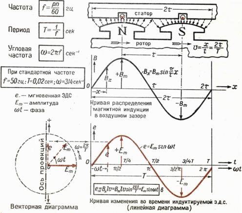
Induction alternator alternator. In induction alternating current generators, the mechanical energy turns into electrical. The induction generator consists of two parts: movable, called a rotor, and a fixed, which is called a stator. The generator action is based on the phenomenon of electromagnetic induction. Induction generators have a relatively simple device and allow you to obtain large currents at a fairly high voltage. Currently there are many types of induction generators, but they all consist of the same major parts. This is, first, an electromagnet or a permanent magnet that creates a magnetic field, and, secondly, a winding consisting of sequentially connected turns, in which a variable electromotive force is induced. Since the electromotive forces, induced in series connected turns, are folded, then the amplitude of the electromotive force of induction in the winding is proportional to the number of turns in it.
 Fig. 6.9 Fig. 6.9 |
The number of power lines penetrating each round is continuously changing from the maximum value when it is located across the field, to zero, when the power lines slide along the turn. As a result, when the turn is rotated between the magnet poles after each half-turn, the current direction changes to the opposite, and alternating current appears in the twist. In the external circuit, the current is given by sliding contacts. To do this, the contact rings attached to the ends of the winding are strengthened on the winding axis. Fixed plates - brushes are pressed to the rings and communicate with an external chain winding (Fig. 6.9).
Let the coil of the wire pumped in a single magnetic field with a constant angularity. Magnetic stream, piercing the coil, changes by law, here S. - Torch area. According to the law of Fepadiam in the winding, the electromotive force of induction is guided, which is assessed as follows:
where N. - The number of turns in the winding. Thus, the electromotive force of induction in the winding varies according to the sinusoidal law and the number of turns in the winding and the frequency of comprehension.
In the experiment with a rotating winding, the stator is a magnet and contacts, between which the winding is placed. In large industrial generators, an electromagnet rotates, which is a rotor, while the windings in which the electromotive force is presented, are laid in the stator grooves and remain fixed. On thermal power plants for rotation of the rotor, steam turbines are used. Turbines, in turn, are brought into rotation of water vapor jets obtained in huge steam boilers due to the burning of coal or gas (thermal power plants) or the decay of the substance (nuclear power plants). On hydroelectric power plants, water turbines are used to rotate rotor, which are rotated with water falling from a high height.
Electric generators play a crucial role in the development of our technological civilization, since they allow you to receive energy in one place, and use it in another. Steam machine, for example, can convert the coal combustion energy into a useful work, but it is possible to use this energy only where coal fire and a steam boiler are installed. The power plant can be accommodated very far from electricity consumers - and, nevertheless, supply plants, at home, etc.
They tell (most likely, this is just a beautiful fairy tale), as if Faradays demonstrated the prototype of the electric generator John Saw, the chancellor of the UK treasury, and he asked the scientist: "Well, Mr. Faraday, all this is very interesting, and which of all this is a lot?".
"What is fat? - Allegedly surprised Faraday. - Yes, you know, sir, how many taxes this thing will bring to the treasury over time?! "
Transformer.
Transformer. The electromotive force of powerful generators of power plants is large, while the practical use of electricity requires most often not very high stresses, but the transfer of energy, on the contrary, very high.
To reduce losses for heating wires, it is necessary to reduce the current strength in the transmission line, and, therefore, to save the power to increase the voltage. The voltage generated by the generators (usually about 20 kV) is raised to a voltage of 75 kV, 500 kV and even to a voltage of 1.15 mV, depending on the length of the power line. Raising voltage from 20 to 500 kV, that is, 25 times, reduce losses in line 625 times.
The transformation of an alternating current of a certain frequency at which the voltage increases or decreases several times with almost no power loss, is carried out by an electromagnetic device that does not have mobile parts - an electric transformer. Transformer is an important element of many electrical appliances and mechanisms. Charging device And the toy railways, radio and televisions - transformers that reduce or increase the voltage everywhere. Among them are found both completely tiny, no more peas and real colosses weighing hundreds of tons and more.
 Fig. 6.10 Fig. 6.10 |
The transformer consists of a magnetic pipeline representing a set of plates that are usually made from ferromagnetic material (Fig. 6.10). On the magnetic conductory there are two windings - primary and secondary. The one of the windings that connects to the source of alternating voltage is called primary, and the one to which the "load" is attached, that is, the electricity consuming instruments are called secondary. The ferromagnet increases the amount of magnetic field strength lines of approximately 10,000 times and localizes the flow of magnetic induction within itself, due to which the transformer winding can be spatially separated and still remain inductively connected.
The transformer effect is based on mutual induction and self-induction phenomena. The induction between the primary and secondary winding is mutual, that is, the current flowing in the secondary winding induces the electromotive force in the primary, just as the primary winding induces the electromotive force in the secondary. Moreover, since the turns of the primary winding cover their own power lines, the electromotive power of self-induction occurs in them. The electromotive power of self-induction is also observed in the secondary winding.
Let the primary winding be connected to an AC source with an electromotive force, so it occurs an alternating current that creates a variable magnetic flow in the transformer magnetic circuit breed ? which focuses inside the magnetic core and permeates all the turns of the primary and secondary windings.
In the absence of an external nipper, the power is released into zero, that is, the current power is close to zero. Apply to the primary chain Ohm's law: the sum of the electromotive force of induction and voltage in the chain is equal to the product of the current for the resistance. Believing, you can write:, therefore, ![]() where F. - The flow permeating each turn of the primary coil. In the perfect transformer, all the power lines pass through all the turns of both windings, and since the changing magnetic field generates the same electromotive force in each turn, then the total electromotive force induced in the winding is proportional to the total number of its turns. Hence,
where F. - The flow permeating each turn of the primary coil. In the perfect transformer, all the power lines pass through all the turns of both windings, and since the changing magnetic field generates the same electromotive force in each turn, then the total electromotive force induced in the winding is proportional to the total number of its turns. Hence, ![]() .
.
The voltage transformation coefficient is equal to the ratio in the secondary chain to the voltage in the primary chain. For amplitude voltage values \u200b\u200bon windings, you can write:
Thus, the transformation coefficient is defined as the ratio of the number of turns of the secondary winding to the number of turns of the primary winding. If the coefficient, the transformer will increase, and if low.
The ratio written above, strictly speaking, applicable only to the perfect transformer, in which there is no scattering of the magnetic flux and there are no energy losses on Jowlelo heat. These losses can be associated with the presence of active resistance of the windings themselves and the occurrence of induction currents (Foucault currents) in the core.
Toki Foucault.
Toki Foucault. Induction currents can also occur in solid massive conductors. In this case, the closed induction current circuit is formed in the thickness of the conductor itself when it moves in a magnetic field or under the influence of an alternating magnetic field. These currents are named by the name of French physics Zh.B.L. Foucault, which in 1855 discovered the heating of ferromagnetic cores of electrical machines and other metal bodies in a variable magnetic field and explained this effect by exciting induction currents. These currents are currently called vortex currents or Fouco currents.
If the iron core is in a variable magnetic field, then in it under the action of the induction electric field there are internal vortex currents - Foucault currents leading to its heating. Since the electromotive force of induction is always proportional to the frequency of oscillations of the magnetic field, and the resistance of massive conductors is small, then at high frequency in the conductors will be highlighted, according to the law of Joule-Lenz, a large number of Heat.
In many cases, Foucault currents are undesirable, so you have to take special measures to reduce them. In particular, these currents cause heating ferromagnetic cores of transformers and metal parts of electrical machines. To reduce the losses of electrical energy due to the occurrence of vortex currents, the cores of transformers are made not from a solid piece of ferromagnet, but from separate metal plates, isolated from each other by the dielectric layer.
 Fig. 6.11 Fig. 6.11 |
The vortex currents are widely used for metal melting in the so-called induction furnaces (Fig. 6.11), for heating and melting metal blanks, obtaining particularly clean alloys and metals compounds. For this, the metal blank is placed in the induction furnace (the solenoid, which is passed by alternating current). Then, according to the law of electromagnetic induction, induction currents occur inside the metal, which warm the metal and can melt it. Creating a vacuum in the furnace and applying levitational heating (in this case, the power of the electromagnetic field is not only warming up the metal, but also hold it in a suspended state out of contact with the surface of the chamber), especially clean metals and alloys are obtained.
Content:
When people looked at the possibilities of electricity, immediately began to invent, as if seriously put this interesting energy into service. And a whole range of devices, devices, installations capable of creating at two metallic ends electrical voltage. To the ends immediately screwed two bolts and began to hang everything that was now caused by a lot of interesting effects. These devices were generally called electricity sources, or generators. And the fact that they were connected - an electrical chain. And as they grow the chains and classes with them more and more significant and permanent space in human life, they began to be called electrical networks.
It is the generators that created all our electric adventures. What is the principle of operation of the alternator of the AC differ from the principles of the work of the first sources? Some reliability and constancy originating from the reliability and universal availability of the energy from which they produce electricity. This is a mechanical movement. And we have the whole world full of movement. And it was quite natural to force the rotors to spin, and the movement for this to take from something else. From heat. Fuel combines, the rotor spins - the current generator works.
The initial source was the product of the first experiments. Chemistry (batteries), electrification (electrophore machines) - all this is somehow weak. Because it is disproportionately expensive, relatively with the amount of energy that the network required. First lighting, and then almost immediately tram. Here is a tram and pushed current generators forward in development.
The tram line is where electric power itself produces movement. The advantage of this approach was a very convenient supply of such "fuels" to large quite distances. And very organically fitted in the cost of making the tram line itself. When they put iron tracks, which is not to be laid along them and the wire is also linked to the trams that can now be on the line anywhere and with the same ease of receiving this energy.
The conversion turned out to be symmetrical: the alternator device is almost the same as the engine. Only the generator appointment is to produce electricity, rotating the rotor, and another electricity twists almost the same rotor, and he is already the wheel tram.
About such transmission of energy of the mechanics of past centuries only dreamed. After all, once with the help of a water wheel, the trees of processing machines in the whole shops are rotated. And the mechanical energy was also transmitted, mechanically: with the help of shafts, pulleys, belts, gear ... Immediately - two wiring. And in the case of trams in general one. The second is the rails themselves.
Current alternating and current permanent
At first, the electric current was opened when they saw that he showed himself, acts. Then they only found that the current is permanent, but maybe variable.
Actually generation of current always and comes from change Magnetic field passing through the winding. And the voltage that occurs simply must be variable. Because it is technically simply unthinkable to make the magnetic field change strictly uniformly. The sources of current obtained by another basis were based on stationary processes (or quasistationary - given the discharge of batteries), so they gave an exceptionally constant current. When the telegraph was invented - probably, the first electrical invention, which pushed to the creation of large-scale electrical lines, - this very current in them was constant, albeit intermittent. Constant current is not very high voltage It gives huge losses from resistance in conductors in the transmission to long-distance distances. Already Samuel Morza came up with this, when I stretched my first telegraph line in 1844 from Baltimore to Washington. With a friend, they managed to cope with it using the "active gain" of the signal using the relay.
Tram lines, as you know, at first inherited this tradition - to eat by a constant electric shock, although the design of the magnets and the conductors rotating in their field, being used as an alternator, it is easier and easily produced.
The purpose of the generator is the production of voltage, permanent and variable, hence its device and the principle of operation.
And the types of the produced voltage and determined the structure and principle of the operation of the generators.
Therefore, both type generators differ - the DC generator and the alternator of the AC.
In the DC generators of this constancy, it is reached with structural triggers: by creating a certain configuration of the magnetic field, by increasing the number of anchor frames in the rotor, in which the potential difference is indispensable and removing it with a multi-contact manifold, by organizing special excitation current modes on special excitation currents installed on the magnets of the stator, etc.
But it turned out, it is easier to achieve the same effect by another: the induction alternator of the AC voltage produces, and then it is "straightened" by the usual scheme of the diode rectifier. What makes, for example, a car generator.
Principle of operation of the device
The AC generator is a mechanical-induction machine that creates an alternating electrical voltage on its output contacts in response to rotation of its rolling part by an extraneous force.
The movable part of the generator (or alternator) is called a rotor, a fixed - stator.
Two parts of the generator produce the following: One of them creates a magnetic field, and the second part contains conductors located in such a way that when changing them in this magnetic field (we call it generating), the potential difference occurs at their opposite ends. It is removed and transferred from these conductors for weekends.
Types of alternating current generators
From here there are two variants of alternator designs, in which:
- the generating magnetic field is created in the stator and motionless;
- the generating magnetic field is created in the rotor and rotates with it.
In any case, the voltage arising from the generation must be removed not from the part of the generator, where the magnetic field is created, and with the opposite.
Initially - starting with experiments on the rotation of the frame from the conductor in a stationary magnetic field - the rotor and served to guide in its windings (or framework) of electrical induction, which generated the movement of electrons to different ends of these conductors, which has occurred.
Apparently, this is due to the fact that the magnets chose more and squeeze in order to create a strong field with a large gradient, and the current frames were completely lungs. But now the rotor, and the stator - this is accurately impressed with each other massive parts. The voltage from the rotor rotor (or anchor) must be removed using a special mechanism and send to fixed outputs. Such a mechanism is called a collector (from lat. "Collector"), in it fixed spring-loaded brushes, "extended" from the stator are tightly pressed against rotating along with the rotor contacts.

Perhaps, it is constructive that the narrowest part of the electric motors and generators. It requires special execution, when rotating it, it is erased from poor contacts - with erased contact plates, or gaps between them, or broken brushes (which are usually made from graphite - and there is a conductive dust from it) - it starts with a sponge of rotation, and this is nobody I do not like.
Therefore, the most convenient variant of alternators is the second. This is when the magnetic field rotates a rotor, and the voltage occurs in a fixed stator. And it is not necessary to remove any intricate way.
Single-phase and multiphase
Principle of operation
The magnetic field can be driven (change, rotate) over one system of conductors (having two poles) or over several.


From the picture it is clear how the simplest alternator is arranged. What is the generator? The main parts are the rotor and the stator. We see that the rotor with the N-S migrant installed in it rotates. At the same time, the magnet pole, then n, then s, alternately completely close to the coils with windings. The windings are sequentially connected to each other and then with output contacts. The direction and flow of the magnetic field passing through the windings is changed when rotating. What is the variable voltage on the output contacts with the frequency f. Rotation of the rotor. There is a voltage generating, and when connected to the load contacts, an alternating current of the frequency occurs f.
This scheme is the simplest. It is just a little more complicated than those frames that have twisted once in the field of two magnets. Only now, on the contrary, the magnet installed on the rotor rotates, and the fixed coils give voltage.
The voltage is obtained by a sinusoidal, maxima and a minimum, when the magnet poles take place near the coils - about them the flow of the magnetic field is the most carnal, and therefore the most fast change Fields. And on contacts at this time, the maximum voltage U, or - U will be hosted. When the rotor turns in such a way that the magnet will pass a horizontal position, output voltage will cross the zero value.
Three-phase alternator
However, we see that there are still a lot in this simple electric car. free space. Well, you can put a few steam on the perimeter of the stator, and several pairs of coils. But then you will have to remove individual contacts from each pair of coils, so that the voltages of different pairs are not quenched each other. It turns out as several generators in one, each of them will give a sinusoidal voltage, but since the coils are turned relative to each other, and the sinusoids will be shifted at exactly such an angle, on which pairs of coils are shifted relative to our original.


The coils are distributed over the perimeter of the stator evenly, that is, each other is removed to the angle 120⁰. Exactly such a phase shift is also in voltages. U1 voltage with zero shift (this is our first pair of coils), voltage U2 - 120⁰ and voltage U3 - 240⁰.
Such tension is called three-phase. It is possible to transmit it with unified system Wires are three wires on one to each phase, and zero of all three is combined into one. This can be done in two ways: connecting the windings of the coils by the type "Triangle" or "Star".
You can come up with other alternating voltage generation schemes, for example, by installing not three pairs of coils, but only two. Then the difference between the phases between them will turn out in 90⁰.
The use of a three-phase generation system found.
In the consumption of three-phase voltage, individual phases are often distinguished and distribute them to different consumers. When consumers are much, it is possible to randomly "distribute" phases - on average the same load on all phases is usually obtained. But it should be tracked. Because if consumption in different phases is very different or it behaves very unevenly in time, such a phenomenon occurs as "skew phases". Voltage in different phases begins to be different. And this leads to very many poor consequences: electricity overruns, failure of transformers, electrical appliances, engines. At the power station - to the fall of the efficiency of the generators (they will begin to "chrome") and even the failure of electricity generators. To minimize this kind of damage, the zero wire is usually ground, but the energy of such an unpleasant phenomenon should be monitored.
The excitation of the generator
The real generator differs from here and the fact that as a source of magnetic field, it is useless to use permanent magnets. The magnetic field in the industrial installation should be strictly defined and strictly withstanding tension. And how to achieve strictly equal magnet tension at different phases in a three-phase alternator of alternating? Otherwise, the voltages on them will be different, and there will be the "ever chromavering" phases. Therefore, electromagnets with cores are used on the rotor instead of magnets. A constant voltage is supplied to them, and during the operation of the generator excite the electromagnetic field of strictly given intensity. A constant voltage is fed from an independent source - it may be a battery or other DC source. Here again there is a problem: or hang over the rotor also the battery to power the excitation coils, or again bother with collectors to transmit excitation voltage. The solution can be called Solomon: Make on one rotor, as it were, two generators at once, only the second feeds the current winding over the first. And in the stator, accordingly, even electromagnets are added to excite the magnetic field in this second generator, the current from which is used only in the rotor itself, therefore, it is not needed outside the outside. And do not like any collectors for his removal. This design began to be called "Brushless Synchronous AC Generator".
It is called synchronous because both sources are the excitation current generator, and the device generator, which gives the final result - the output voltage, operate simultaneously on the same rotor.
Using the excitation current, you can affect the voltage, which gives a device generator: with an increase in the excitation current, the magnetic field excited by the rotor is enhanced accordingly, why the main generator windings will produce an alternating voltage of higher amplitude.
This is used to adjust the voltage, since the rotor speed cannot be changed, and the frequency will change otherwise, and it is assigned hard technical characteristics all our electricity network.
Our power system produces voltage with a frequency of strictly 50 Hz, and produce generators of power plants - they all rotate their rotors at a speed of 50 Hz. And the design of the rotor displays voltage, variable 50 times per second.
However, in many cases, where the high accuracy of the frequency of the energy produced is not critical, asynchronous generators are used. They are easier and cheaper than synchronous, but provide voltage with a large variation of parameters. It does not matter where it will still be transformed into permanent schemes.
The generator node is an electric motor designed to convert mechanical energy into electrical. Depending on the type and purpose of the dimension, the device and the principle of operation of the AC generators may differ.
[Hide]
How does alternator working?
The operation of the generator is to create an electromotive force in the conductor under the action of a changing magnetic field.
Scheme and device of the simplest generator
By design, the electric generator includes the following elements:
- the rotating inductor component, called the frame;
- driving brush part;
- collector equipment equipped with brushes designed to remove voltage;
- a magnetic field;
- contact rings.
Scheme of the simplest alternator of alternating current
Operating principle
The formation of the electromotive force in the windings of the stator mechanism is carried out after the appearance of the electroopol. For the latter, vortex education is characteristic. These processes occur as a result of changing the magnetic flux. Moreover, the latter changes due to the rapid rotation of the rotary mechanism.
The current from it enters the electrical panel by means of contact elements made in the form of sliding parts. For a more simplified voltage passage to the ends of the winding, a rings is connected. Mixed brush elements are connected to these contact components. With their help between wiring and winding a rotary device, a connection appears.
In the turns of the magnetic element, the field formation occurs, a short amount of a small value is formed in it. Compared to the voltage, which gives the simplest generator unit to the external electrical panel. If the node is characterized by a small power, then in it the field forms a permanent magnet, which can scroll. Thanks to such a device and the principle of operation of the alternator, the entire system is generally simplified. Therefore, brushes and contact elements can be removed from the design.
The Top Generators Channel clearly and schematically showed the principle of the functioning of the aggregate.
The main types of alternators of alternating current
Between themselves devices to generate voltage, are divided into synchronous and asynchronous. They can be used in various spheres of vital activity, but will work according to a different principle.
Synchronous generator
One of the properties of this type of device is that the frequency of the current that it reproduces is proportional to the rotational speed of the rotary mechanism.
With each other, synchronous units are divided into several types:
- Increased frequency. The principle of functioning of the device is the process of changing the magnetic flux achieved by rotating the rotary mechanism regarding the fixed stator. This type of aggregates is used mainly to power the antennas of long-wavelength stations at a distance of up to 3 km. Connect devices to work with shorter waves will not work, since it is necessary to increase the frequency value.
- Hydro-turbine aggregates work through the activation of the hydraulic turbine, which leads to the movement of the node. In such devices, the rotary mechanism is installed on one pulley with a wheel of a turbine element. Its power can be up to 100 thousand kW, if the speed of rotation is 1500 revolutions per minute, and the voltage is up to 16 thousand V. by weight and dimensions, this type of aggregates is considered the largest, since in them the diameter of one rotor is 15 meters. The magnitude of the power of the turbine circle is influenced by three parameters - the speed of rotation, the length of the electrolene, as well as the maximum moment of the rotary mechanism.
- Steam turbine aggregates, which are powered by activating the steam turbine. This type of devices functions with a speed of rotation of 1.5-3 thousand revolutions per minute and they are two-way and four-band. The rotary mechanism is made in the form of a large iron cylinder equipped with rectangular grooves, an excitation winding is located inside the element. The body of the stator device is always inconsectable and made of steel. The total diameter of the unit is up to 1 meter, but its rotor length can be up to 6.5 m.
Scheme and device
The synchronous unit structurally includes two main elements:
- Rotor. This is the movable component of the equipment. It is designed to convert the system of rotating electrical magnets that feed from an external source.
- Stator mechanism or fixed component of the unit. In the winding of this device, an EDC appears through the formation of the magnetic field, which goes to the outer electrical power supply equipment. Thanks to constructive features Sliding contacts are not used in the load circuits of synchronous electrical generators. The magnetic flow from the equipment that appears by rotating the rotor is excited from a third-party source. The latter is mounted on a common shaft or can be connected to it using a clutch or belt transmission.
Schematic device of a synchronous generator unit
Features of work
The principle of operation may differ slightly depending on the type of device - the appeater and uncommon. The number of pairs of pole elements of the rotary mechanism is determined by the speed of rotation of the node. If the frequency of the EDC forming is 50 Hz, then at 3 thousand rpm, an innovable device has a single pair of poles. In the aircraft units rotating at 50-750 revolutions per minute, the number of pairs of pole elements will be from 60 to 4.
In low-power synchronous units, the power of the excitation winding is carried out by means of exposure to the rectified current. Electroup appears as a result of activation transformer deviceswhich are included in the overall load circuit of the node. It also includes a semiconductor straightening unit that can be assembled according to any scheme, but usually like a three-phase bridge. The main electrical panel includes a winding of an aggregate excitation with an adjusting rheostat device.
The procedure for self-excitation of the equipment is as follows:
- When the installation is started, small EMF is formed in the magnetic component, this is due to the phenomenon of residual induction. At the same time, a current appears in the working winding of the unit.
- As a result, the EMF is formed in secondary electrocessing transformer devices. And a small current appears in the electrocups, which helps strengthen the general induction of the magnetic field.
- An increase in the EDC parameter is carried out until the magnetic system of the unit will not be excited to the end.
Asynchronous generator
Such a node is a device that produces electricity using the principle of action of an asynchronous engine. This type of aggregates is referred to as induction. The asynchronous device provides an operational rotation of the rotor mechanism, and its rotational speed is much higher compared to synchronous. A simple engine can be used as a generator installation without additional settings.
Asynchronous units are used in different fields:
- for motor wind power stations;
- for the autonomous nutrition of residential premises and private houses or as miniature hep stations;
- for inverter welding aggregates;
- for the purpose of the organization uninterrupted power from alternating current.
Scheme and device
Schematic connection of an asynchronous unit
The main components of this type of device are the stator mechanism and the rotor. The first is fixed, and the second is scrolled inside it. The rotor is separated from the stator mechanism by the air gap. To reduce the magnitude of the vortex currents, the cores of the components of the elements are made from individual sheets of electrical steel. Their thickness depending on the manufacturer can be from 0.35 to 0.5 mm. The sheets themselves are oxidized in the manufacture, that is, they are subject to heat treatment, which allows you to increase their surface resistance.
The core of the stator mechanism is installed inside the bed, which is the outer part of the unit. On the inside of the details there are grooves, there are winding in them. Stator electrobid is often performed from coils with a small step. It uses a copper insulated conductor.
Features of work
Asynchronous type of engines produces electricity with an increased speed of scrolling the rotary mechanism. This parameter is always higher than synchronous units. When scrolling a rotary device and generating electricity, a strong torque will be required. If the engine uses the so-called perpetual idle stroke, this will ensure an equal speed of scrolling over the entire operation resource of the installation.
Connection schemes
By the number of phases used, all generator units are divided into two groups:
- single-phase;
- three-phase.
Single-phase generator
Connection diagram with single phase
This type of device is used to work with any electricity consumers, the main thing is that they are single-phase.
Self simple designs consist of:
- magnetic field;
- scrolling frame;
- collector device designed to remove current.
Due to the presence of the latter as a result of frame scrolling through brushes, constant contact with the frame is formed. The current parameters that changes taking into account the harmonic law will be different and are transmitted to the brush node, as well as in the voltage consumer scheme. To date, single-phase units are the most popular type of autonomous power supply. They can be used to connect almost all household appliances.
Three phase generator
This type of devices refers to the class of universal, but more expensive units. Distinctive feature three-phase generators lies in the need for permanent and expensive maintenance. In spite of this, this type Installations got the greatest distribution.
This is due to the following advantages:
- The aggregate is based on a rotating circular magnetic field. This provides the possibility of good savings when developing equipment.
- Three-phase generators consist of a balanced system. This provides the resource of the operation of the unit as a whole.
- In the work of the three-phase device, two voltages are simultaneously used - linear and phase. Both are used in a single system.
- One of the main advantages is increased economic indicators. This ensures a decrease in the material intensity of power wires, as well as transformer units. Thanks to this feature, the procedure for transmitting electricity over long distances is simplified.
Connection Scheme "Star"
This type of connection implies the electrical connection of the windings at a certain point, which is called "zero". When this connection is performed, the load to the generator node can be submitted by three or four cables. Conductors from the start of the windings are considered linear. And the main cable that comes from the zero point is zero. The voltage parameter between the conductors is considered linear (this value is 1.73 times compared to phase).
Star type scheme for connecting three-phase equipment
One of the main features this option is the equality of currents. The four-wire type "Star" with a neutral cable is considered the most common. Its use allows you to prevent phase skew when connecting asymmetric load. For example, if it is active on one contact, and on the other is reactive or capacitive. When using this option, the maximum security of the included electrical equipment is ensured.
Connection schemes "Triangle"
This connection method is a consecutive connection of the three-phase unit windings. The end of the first winding must be connected to the beginning of the second, and its contact is with the third. Then the conductor from the winding at number 3 is connected to the beginning of the first element.
With this scheme, line cables are removed from the winding points. The parameter of the linear voltage in size corresponds to phase. And the value of the first current is higher than 1.73 times. The described properties are relevant solely in the event of a uniform load of the phases. If it is uneven, then the parameters must be recalculated by a graphic or analytical way.
Electroschemes of the connections of the unit "Triangle"
Features of generators with different types of engine
Automotive and household settings can be separated in each other according to the type of fuel on which they function. The generator node can work on gasoline or diesel.
Benzogenerators
In such devices, the source of mechanical energy is the engine. The unit refers to the class of four-pin carburetor engine. In the benzogenerators, engines are used, calculated on 1-6 kW. You can find units designed for operation at 10 kW, with their help, you can provide nutrition of all light and electrical appliances in a private house.
Benzogenerators can boast a low cost and a long service life, although compared to diesel - they are slightly smaller. The selection of the unit is carried out taking into account the loads, in the conditions of which it will function. If the node works with a large starting current and is used for electrical welding, it is better to prefer synchronous devices. When choosing an asynchronous type of unit, the engine will be able to cope with starting currents. But it is important that the generator installation is fully loaded, otherwise the fuel will be consumed inexpedient.
The Olifer TV channel spoke about the choice of aggregates for a private house in accordance with the type of combustible, on which it will be used.
Diesel generators
Such an aggregate drives a motor operating on a diesel.
It is used:
- mechanical component;
- panel with buttons designed to control;
- fuel supply system;
- cooling unit;
- the lubrication system of rubbing components and nodes.
The power of the generator set is fully determined by the same parameter of the engine itself. If it is low, for example, for washing household electrical equipment, it is better to give preference to gasoline installations. The diesel type of aggregates is advisable to use where high power is required. Internal combustion engines are typically used with the top valve installation. They have more compact sizes, as well as high reliability.
In addition, diesel engine in operation is released less toxic gases, dangerous to human health, and more convenient in terms of repair. Specialists are recommended to give preference to aggregates whose body is made of steel, as the plastic has a smaller use resource.
The generator diesel plants that are not equipped with brushes are more reliable.
The voltage that they produce is more stable. On average, if the tank is filled with diesel flammable, it will provide the ability to work the generator for seven hours. If the unit is installed stationary, its design can be supplemented with an external tank for fuel bay.
Channel "Current factory" demonstrated the work of the diesel unit used to ensure the energy of the private house.
Inverter generators
Electrical energy production is carried out similarly as on any classic generator model. First of all, alternating current is produced. It is straightened and fed to the invertor node, and then converted to variable again, only with the necessary technical parameters.
The aggregate is based on an electronic module, which includes:
- rectifier node;
- microprocessor device;
- converter mechanism.
By type of output voltage, inverter units can be divided into:
- Rectangular. This type of devices is considered the cheapest. Its energy is enough only for the washing of power tools and low-power devices.
- Devices with a trapezoidal signal. Can be used to feed most electrical appliances, except for highly sensitive technology. The cost of such aggregates is average.
- Devices working with sinusoidal voltage. Such generators are characterized by stable characteristics and are suitable for most electrical appliances.
Inverter units can function without interruption or intervals. As objects of energy consumption, institutions are usually advocated, where voltage differences cannot be allowed.
The main advantages of inverter installations:
- small sizes and weight;
- low fuel consumption as a result of adjusting the production of a certain amount of electricity required at a particular point in time;
- inverter units can function during a short time interval with overload.
- high cost of devices compared to classic generator installation options;
- increased sensitivity to temperature changes in the electronic component;
- low level of installation power;
- expensive repair of the electronic module during its breakdown.
The use of inverter devices is relevant in the case when the required power value is not more than 6 kW. If the unit is used on an ongoing basis, it is better to give preference to the classic type.
The Channel "Garage Kakhovka" tested the gasoline installation of an inverter class from the manufacturer "Pilod".
How to make an alternator with your own hands
For independent manufacture of an asynchronous unit, you will need the following:
- Motor. The engine can be built with your own hands, but this procedure is too long and time-consuming. Therefore, it is better to use an aggregate from the old non-working household electrical equipment. The optimal option will be the use of the engine from the drainage pumping device, washing machine either vacuum cleaner.
- Stator mechanism. It is recommended to purchase a ready-made device equipped with winding.
- Set of electrical wires.
- The tape is allowed to use heat shrink tubes.
- Transformer node or rectifier block. This element will be required if the energy of the AC generator output will have different power.
Before starting work, you need to make several manipulations that will allow you to correctly calculate the power parameter of the unit:
- The engine used is connected to the power grid to determine the speed of rotation. To accomplish this task, a special device is required - tachometer. After reading information, the value obtained must be recorded and adding to it another 10%. This is a compensatory value. If you add 10% to the speed of rotation, it will prevent the unit overheating during operation.
- The selection of condenser elements is performed, taking into account the required power value. If there are difficulties at this stage, you can use the table.
- The generator installation during operation produces electricity, respectively, it is necessary to think in advance to ground the device. With its absence and poor-quality isolation, the unit is not only extended faster, but also may be dangerous for humans.
- After preparation, the assembly procedure is performed, it does not take a lot of strength. The engine that will be used is based on, condenser elements are connected in accordance with the scheme. It contains the order of connecting components. It is necessary to consider that the magnitude of the capacity of each condenser part corresponds to the previous device.
 Scheme assembly simple alternator
  Capacuation Table Capacitance for Aggregate
The resulting unit will be able to provide energy with an electric saw, circular or grinder, i.e. any low-power tool.
When using a self-made alternator, the AC cannot be allowed to overheat the engine, otherwise it will lead to its breakdown and even an explosion.
In the process of assembly and operation, the following nuances should be taken into account:
- If the efficiency falls directly proportional to the duration of work, this is the norm. This nuance is associated with the fact that periodically the generator unit should relax and cool. It is important from time to time to reduce the engine temperature to 40 degrees Celsius.
- Since automation is not used in a simple scheme of the device, the consumer must control all the operation processes itself. From time to time, the aggregate must be connected to the measuring equipment - tachometer, voltmeter.
- Before assembly, you need to correctly choose the electrical appliances in accordance with the calculation of its technical parameters and properties. The diagram is most simple in terms of implementation.
Video "Principle of operation of the generator device"
The Halyk Smart channel spoke about the nuances of the functioning of the AC unit.
The term "generation" in electrical engineering came from Latin. He denotes "Birth". In relation to the energy, we can say that the generators are called technical devicesengaged in the production of electricity.
In this case, it is necessary to make a reservation that it is possible to produce an electric current by converting various types of energy, for example:
chemical;
light;
thermal and others.
Historically, it was found that the generators call structures that convert the kinetic energy of rotation into electricity.
By type of electricity produced, generators are:
1. DC;
2. A variable.
Physical laws that allow you to create modern electrical installations to generate electricity due to transformations of mechanical energy, open by scientists Ersteted and Faraday.
In the design of any generator, it is implemented when an electric current is placed in a closed frame due to the intersection of it with a rotating magnetic field, which is created in simplified household models or excitation windings on industrial products of elevated capacities.
When the frame is rotated, the magnetic flux value changes.
The electromotive force induced in the twist depends on the rate of change of the magnetic flux, which pierces the frame in the closed circuit S, and is directly proportional to its value. The faster the rotor is rotated, the higher the magnitude of the produced voltage.
In order to create a closed loop and remove the electric current from it, it was necessary to create a collector and a brush node that provides permanent contact between the rotating frame and stationaryly located part of the circuit.

Due to the design of spring-loaded brushes, pressed against the collector plates, the electric current is transmitted to the output terminals, and then it enters the network of the consumer.
Principle of operation of the simplest DC generator
When the frame is rotated around the axis, its left and right halves cyclically pass around the southern or north pole of magnets. In them, each time the current directions are changed to the opposite so that each poles they flow in one direction.
In order for a permanent current in the output circuit, a semiring unit was created on the collector node for each halve of the winding. The brushes adjacent to the ring remove the potential of only its sign: positive or negative.
Since the semiring of the rotating frame is open, then it creates moments when the current reaches the maximum value or missing. To maintain not only the direction, but also the constant value of the produced voltage, the frame is manufactured by specially prepared technology:
it uses not one round, but several - depending on the magnitude of the planned voltage;
the number of the framework is not limited to one instance: they are trying to make sufficient quantities to optimally maintain voltage drops at one level.
The constant current generator, the rotor winding is placed in the grooves. This makes it possible to reduce the loss of the indoor electromagnetic field.
Constructive features of DC generators
The main elements of the device are:
external power frame;
magnetic poles;
stator;
rotating rotor;
switching knot with brushes.

The housing is made of steel alloys or cast iron to give the mechanical strength of the overall structure. An additional challenge is the transmission of a magnetic flux between poles.
The poles of magnets are attached to the body with pins or bolts. Mounted winding.
The stator, called another Yarma or core, is made of ferromagnetic materials. It places winding coil of excitation. Stator core Equipped with magnetic poles forming its magnetic power field.
The rotor has synonym: anchor. Its magnetic circuit consists of chosen plates that reduce the formation of vortex currents and increase efficiency. In the core grooves laid rotor and / or self-excitation windings.
Switching knot With brushes can have a different number of poles, but it is always multiple two. Brushes material usually use graphite. The collector plates are made of copper as the most optimal metal suitable for the electrical properties of current conductivity.
Through the use of the switch on the output terminals of the DC generator, a pulsating type is formed.

Main types of DC generators designs
By type of power, the excitation winding distinguish devices:
1. With self-excitation;
2. Working on the basis of independent inclusion.
The first products can:
use permanent magnets;
or work from external sources, such as batteries, wind installation ...
An independent enable generators work from their own winding, which can be connected:
sequentially;
shunts or parallel excitation.
One of the variants of such a connection is shown in the diagram.

An example of a DC generator can serve as a design that used to be used before the automotive technique. Its device is the same as the asynchronous engine.

Such collector designs are capable of working in engine or generator mode simultaneously. Due to this, they were distributed in existing hybrid cars.
The process of forming an anchor reaction
It occurs in idle mode when incorrect setting Efforts of pressing brushes creating non-optimal regime Their friction. This can lead to a decrease in magnetic fields or the emergence of a fire due to increased education of sparks.
Ways to reduce it are:
compensation of magnetic fields due to the connection of additional poles;
setting the position of collector brushes.
Advantages of DC generators
These include:
lack of losses for hysteresis and the formation of vortex currents;
work in extreme conditions;
low weight and small dimensions.
Principle of operation of the simplest alternator
Inside this design, all the same details are used as the previous analogue:
a magnetic field;
rotating frame;
collector knot with brushes for current removal.
The main difference lies in the device of the collector node, which is created so that when the frame is rotated through the brushes, contact with its half frame is constantly created without cyclical change of their position.
Due to this current, replacing under the laws of harmonics in each half, completely unchanged is transmitted to the brushes and then through them into the consumer scheme.

Naturally, the frame is created by winding not from one turn, but calculated by their quantity to achieve optimal voltage.
Thus, the principle of operation of permanent and alternating current generators is general, and the differences in the design are made:
collector node rotating rotor;
configuration windings on the rotor.
Design features of industrial alternators of alternating current
Consider the main parts of the industrial induction generatorwhere the rotor receives a rotational movement from a nearby turbine. The stator design includes an electromagnet (although the magnetic field can be created by a set of permanent magnets) and the rotor winding with a certain number of turns.
Inside each turn, an electromotive force is induced, which consistently folds in each of them and forms on the output clamps the total voltage value issued on the power scheme of the connected consumers.
To increase the emission amplitude at the outlet of the generator, use the special design of the magnetic system, made of two magnetic cores due to the use of special varieties of electrical steel in the form of elevated plates with grooves. The windings are mounted inside them.

The generator casing is a stator core with grooves for placing a winding that creates a magnetic field.
Rotating on the bearings, the rotor also has a magnetic circuit with the grooves, inside which the winding is mounted that receives an induced EMF. Usually, a horizontal direction is selected to accommodate the rotation axis, although there are designs of generators with a vertical arrangement and the corresponding structures design.
Between the stator and the rotor always creates a gap required to ensure the rotation and exclusion of the jam. But at the same time there is a loss of magnetic induction energy. Therefore, he is trying to make the minimum possible, optimally considering both of these requirements.
Located on a single shaft with the rotor, the pathogen is an electrical generator of a direct current, which has a relatively small power. Its appointment: to feed the electricity winding of the power generator in the state of independent excitation.
Such pathogens are most often used with the structures of turbine or hydraulic electrical generators when creating the main or backup method excitation.
The image of the industrial generator shows the location of the collector rings and brushes for removing currents from the design of the rotating rotor. This node under work is experiencing constant mechanical and electrical loads. To overcome them, a complex design is created, which during operation requires periodic inspections and implementation of preventive measures.
To reduce the operating costs created, the other, alternative technology, at which the interaction between rotating electromagnetic fields is also used. Only on the rotor there are permanent or electric magnets, and the voltage is removed from the stationaryly located winding.
When creating a similar scheme, such a design can be called the term "alternator". It is used in synchronous generators: high-frequency, automotive, locomotive and vessels, installations of electric power plants for electricity production.
Features of synchronous generators
Operating principle
The name and distinguishing feature of the action is concluded in the creation of a rigid connection between the frequency of the variable of the electromotive force, are injected in the stator winding "F" and rotation of the rotor.

A three-phase winding is built in the stator, and on the rotor - electromagnet with a core and an excitation winding, powered by DC circuits through a brush collector node.
The rotor is driven by the source of mechanical energy - the drive motor at the same speed. His magnetic field makes the same movement.
The stator windings are subject to the same largest, but shifted by 120 degrees in the direction of electromotive forces, creating a three-phase symmetric system.
When connected to the ends of the circuits of consumers, the currents of the phases begin to operate, which form the magnetic field, rotating in the same way: synchronously.
The form of the output signal inhibited EMF depends only on the law of the distribution of the magnetic induction vector inside the gap between the poles of the rotor and the stator plates. Therefore, it seeks the creation of such a design when the induction value changes according to the sinusoidal law.
When the gap has a constant characteristic, the magnetic induction vector inside the gap is created in the form of a trapezoid, as shown on the graph of the lines 1.

If the shape of the edges on the poles is fixed to the row angular with a change in the gap to the maximum value, then the sinusoidal distribution form can be achieved, as shown by the line 2. This technique and enjoy in practice.
Schemes for excitation of synchronous generators
Magnethodific force arising on the winding of the excitation of the "s" rotor creates its magnetic field. For this, there are different designs of DC pathogens based on:
1. Contact method;
2. Contactless way.
In the first case, a separate generator is used, called the causative agent "B". Its excitation winding is powered by an additional generator on the principle of parallel excitation, called the "PV" trivial.

All rotors are placed on the general shaft. Due to this, they rotate completely equally. Reostates R1 and R2 are used to regulate currents in the pathogen and proportel schemes.
With a non-contact method There are no contact rings of the rotor. Directly on it is mounted a three-phase winding of the pathogen. It is synchronously rotated with the rotor and transmits an electric direct current through a rotating rectifier directly to the winding of the causative agent "B".

The varieties of contactless scheme are:
1. System of self-excitation from its own stator winding;
2. Automated diagram.
At the first method The stator voltage of the stator enters a downstream transformer, and then the semiconductor rectifier "PP", which generates a constant current.
In this method, initial arousal is created due to the phenomenon of residual magnetism.

Automatic self-excitation creation scheme includes use:
voltage transformer TN;
automated ABR excitation regulator;
current transformer TT;
rectifying transformer W;
thyristor converter TP;
block protection BZ.

Features of asynchronous generators
The fundamental difference between these structures is the absence of a rigid connection between the rotor rotation frequencies (Nr) and induced in the winding of EMF (N). There is always a difference between them, which is called "sliding". It is denoted by the Latin letter "S" and express the formula s \u003d (n-nr) / n.
When the load is connected, the generator creates a braking torque for rotation of the rotor. It affects the frequency of EDC generated, creates a negative slip.
The design of the rotor in asynchronous generators is manufactured:
short-circuited;
phase;
hollow.
Asynchronous generators may have:
1. Independent excitation;
2. Self-excitation.
In the first case used external source AC voltage, and in the second - semiconductor transducers or condensers in the primary, secondary or both types of schemes.
Thus, alternate and direct current generators have many general features in the principles of construction, but differ in the constructive performance of certain elements.
 Doesn't Diablo III start?
 How to check the computer to spyware
 Spyware on a computer