Satellite Antenna Corner Corner. Setting up satellite antenna
At this stage, we need to determine the approximate slope of our mirror satellite antenna in the vertical plane.
You can certainly not calculate this parameter. But, the knowledge of the correct tilt of the satellite antenna, will save a novice, with an unsuccessful search signal, from unnecessary assumptions " is the antenna correctly?? "For example, if when setting up, you will strongly reject the antenna mirror to the top (or to the bottom). After all, you will already have a visual idea, how it should stand, and in any case, you will return satellite antenna mirror In the original state, after which, continuing the search.
Although, of course, it will not save from manual setting, but still, will noticeably facilitate the whole process satellite antenna settings (saving at the same time, also time).
Now let's figure out which tilt will be offset mirror satellite antenna.
The slope of the satellite antenna - the calculation of the angle of inclination
Unfortunately because tilt satellite antenna, directly depends on its diameter and shape, in order to calculate this tilt, alas ... it is necessary to make a calculation on special formulas.
I do not want to overload your head, and so already a large number of information. Therefore, here, we will offer three ways:
First method. Do not do any computations now. During the configuration of the vertical position of the antenna, first put it in a vertical position. Then, gradually lower the mirror down (or lift), until the signal from the satellite appears. In principle, all the experienced settings do this.
Second way. Note the angle of inclination of satellite antennas installed next door, For example, on the same house, or balconies and roofs of neighboring buildings.
Third way. To do calculation of the angle of tilt satellite antennaTo do this, use any computer program.
To be more clearly, to determine the antenna inclination, I will use the same program "Satellite Antenna Alignment".
To do this, launch this program, and let's go to the " Offset antenna».
Definition of tilt satellite antenna.
In the satellite selection window, put the one to which the satellite antenna will be configured. In this case, I chose Express AM 22 satellite (photo 2).
Photo 2. Select the satellite to which the satellite antenna will be configured.
Let us exhibit the dimensions of the mirror of your antenna, in the cell "The width of the antenna", and the "antenna height".

Indicate the size of the offset mirror of the satellite antenna.
As soon as we offer the sizes of the antenna, near the image below, the numeric indicator "Requires an antenna", will change its value. In my case, it was 73.20 °.

The slope of the satellite antenna.
Being at the place of installation of the antenna, based on the fact that, insert the original position we will only visually, the slope of the satellite antenna mirror is easier to measure from horizontally, as is done in the program, but from the vertical. If you are expressed by more correct words, it will be an angle angle (declination angle) - that is, the angle of declining the satellite antenna mirrors.

The slope of the satellite antenna, or an angle of decline.
Therefore, to make it more convenient for us to make easy computing. Since the straight angle is 90 ° degrees:
![]()
That is, if we deliver the satellite antenna strictly vertically, then from this position, the antenna mirror must be tilted by 16.80 degrees.
In principle, as we will hold the setting of the satellite antenna in the manual (without any "special-tools"), such accuracy, we have nothing to do. Therefore, take a sheet of paper, draw this angle, and just remember visually its slope.
It turns out ... To start setting up the satellite antenna, on the satellite Express AM 22, it is necessary to initially put it, at 16.80 ° from the vertical position. These values \u200b\u200bare naturally applicable to my case. Perform calculations, and for your option, and just remember these two parameters.
Whatever accurate data, nor give us the Satellite Antenna Alignmen program, we will not fully use this accuracy, as it is to be attached to measure, it seems to us as nothing. After all, all the planes you need to refer, we will only have to represent, which means that we will only measure degrees in thoughts, with their inner "graduate". But, all this, quite enough for our purposes.
And so, the zone of coverage of the chain of satellites visible from the installation site of the satellite antenna, we know the vertical slope of the antenna mirror, we are also known. It is possible in principle, and proceed to the preparation of satellite equipment. But before that, let's give a little bit. I would like to clarify some moments concerning the vertical setting of satellite antenna, which may be met and you.
Satellite Antenna Tilt - Setup
(Description of some moments associated with the vertical setup of the satellite antenna)
In the design of the satellite antenna, the suspension is arranged in such a way that an antenna mirror can be equal to raising, that and lower the maximum angle

Satellite antenna suspension, with an equivalent angle of vertical turn.
But in my practice, there were satellite antennas suspensions, in the design of which, the vertical rotation of the antenna itself was carried out as it were with a slope into one of the parties. Therefore, with such a design, it is important to collect it correctly, in accordance with your geographic location, and even more precisely, depending on your latitude, and the satellite remoteness.
Since, I am on a latitude of equal to 63 °, the slope of the satellite antenna will be 16.80 ° from the vertical, and if they mount an antenna, which has a suspension with the priority of the slope in one direction, then the P-shaped element must be placed as in photo 2, (he Showing a red arrow).

At the same time, into the angle of the move of the satellite antenna mirror, just fit into the slope in "16.80 °", (Fig. 1). In this case, it seems that the antenna itself looks a bit in the ground.
If my location, it would be closer to the equator, for example, by 40 degrees of northern latitude, then in this case, the satellite antenna mirror is raised, and the angle of the stroke should be like in Fig. 2.

In this case, the P-shaped element must be positioned on the contrary, as in photo 3, (here I apologize, I just turned this photo by vertical).
The next moment also concerns the setting of the tilt of the satellite antenna, or rather, to say, the installation of the suspension with a slope in one direction, to the vertical support.
When using a satellite antenna suspension with a downhone priority in one direction, if your location is more remotely from the equator, it must be installed, on the mount, as in photo 4 and photo 5.
Satellite antenna, the suspension of which has a bias in one direction
Installed satellite antenna.
Since in this case, satellite antenna will have some angle of inclination to the bottom. Therefore, the M-shaped element of the suspension, at one end of which the converter is fixed, in the lower part of the design it is necessary to have some free space, which allows you to change this angle of an antenna.
To, more understandably explain, the essence of this problem, which may be met and you, let's try, depicted in photo 4, already configured satellite antenna, mentally install on the vertical support (photo 6 and photo 7).
Homemade vertical satellite support

Homemade vertical support, to install a satellite antenna on a horizontal surface.
By comparing these two images (photo 8), we will see that the angle of the M-shaped element of the suspension (photo 9), rests on the wall of the vertical pipe, and the suspension fastener, while it does not even reach this pipe.

Naturally, if we still fasten this suspension, pulling it to the pipe itself, the angle of inclination of the satellite antenna will change, thereby making no further vertical setting.
Of course, this option is the installation of such a suspension, the vertical support is shown in photo 7, it is quite suitable for those who have an antenna mirror stand almost vertically, or higher. For the rest, when purchasing a satellite antenna, you will have to take into account the problem described above.
Since the satellite antenna itself, as a rule, comes with its regular suspension, it is better to acquire a support for it, depending on the coordinates of the place where this antenna will be installed.
Based on this, when buying a satellite antenna and support, it is already desirable to know the antenna inclination angle for your locality, or rather to say, the range of this angle of inclination.
To find out the tilt range of the satellite antenna, let's take advantage of the Satellite Antenna Alignment program. Explain as always, I will be based on my own example.
Equipment for configuring satellite antenna
The satellite antenna is in its place, connectors connections are installed on the cable, and all preliminary settings are made in the receiver. Whatever we have the opportunity to make further configuration, you need to have free access, to the rear, already suspended satellite antenna.
To position the satellite antenna to the selected satellite, we will need the following equipment to configure:
- 1. A small or portable TV, with support for those outputs, which are on your receiver.
- 4. Connecting cable (LC or HF) corresponding to a satellite receiver and television.
- 5. Wrench and screwdrivers corresponding to the fastening of the converter and satellite antenna suspension.
3. Cut the coaxial cable, for connecting a receiver with a converter, a long approximately 1.5 ... 2 meters, with installed connector connector from both ends (this cable is used only during configuration).
If you do not have, a small portable TV, then, of course, it makes no sense to buy it specifically to configure the satellite antenna. To do without excessive costs, it will be possible to purchase, relatively not an expensive device called "Sat Finder". It is created specifically to configure satellite antennas in domestic conditions. At the time of writing this page, the cost of such an appliance was within 400 ... 700 rubles, which is significantly cheaper, compared to the cost of a portable TV. He, of course, has its advantages, well, unfortunately, there are also its drawbacks. About what is the device, and how to work with it, you can read. If you spend the setting of the satellite antenna for the first time, then still, I would recommend you use the option with the receiver and portable TV. I think so it will be easier for you, and more reliable.
Based on the fact that the installation and configuration of the satellite antenna will explain on its own example, I will use the following equipment and tools:

The digital satellite receiver (in this case, the FTA receiver is suitable for viewing open channels).
Looking at the back panel, you can see that this receiver can be connected to a TV, both at high frequency, from the output of the RF modulator and low, via audio-video connectors of the tulip type.

Portable TV. In principle, any small TV is suitable here. The main thing is that it supports those outputs that are present on your satellite receiver.
Looking at the rear panel of this TV, you can see that it can also be connected, both in high-frequency input and by low-frequency audio-video input.
If the receiver is with you, with the RF modulator, then the need for low-frequency audio-video connectors, disappears, but in this case, the TV must maintain a radio frequency DMW range (although, I do not exclude the option that the RF modulators of some receivers, or the TVs of old models, Can only work in the range of meter waves, in the MV-RAM).
If the receiver has, without a voltage modulator, then low-frequency audio video connectors, on the TV itself, are required.

Catch of coaxial cable (To connect to the converter), a long approximately 1.5 ... 2 meters, and with connector connector installed on this cable from both ends.

LF (low frequency) audio video cable Type Tulip, To connect to a TV for low-frequency output and input.

Radio Frequency Cable (RF), Another name is the high-frequency cable (HF). For an option to connect to a TV on a radio frequency antenna input (only with the VF modulator in the receiver).
In view of the availability of audio-video input in the TV, I will not use this cable.

Wrench and screwdrivers, for tightening the fastener of the suspension and fastening the converter corresponding to your satellite antenna set.
Also, for tightening the connector connector on the satellite converter, you will need a horn key to 11.
And so, the equipment to configure the satellite antenna, and the tool is prepared. In conclusion, we will need, any network extensionto bring to the place of configuration (to the already installed satellite antenna), network voltage 220 volts. On the extension, there must be two outlets for connecting a satellite receiver and portable TV.
Also, to configure the satellite antenna in the horizontal plane, we will be needed, compass.
Connecting equipment for configuring satellite antenna
Now, you can transfer the setup equipment and the tool, to the place of installation of the satellite antenna. The overall diagram of the hardware connection, for subsequent setting, is shown in Fig. one.

Fig. one Total hardware connection scheme for configuring satellite antenna.
Satellite receiver with TV, for convenience, I posted on a small chair (photo 1). The TV itself is preferably located so that when setting up a satellite antenna, you could adjust the direction of its mirror, and look at the TV screen, almost simultaneously.

Photo 1. Connected instrument for configuring satellite antenna.
At the time when photography was made for this page, it was the beginning of winter. Therefore, the temperature on the street, reached minus 7 ... 10 degrees. In such conditions, it is not desirable to use electronic devices that are intended to be operated in room temperature. But this means that the configuration of the satellite antenna will have to be transferred for a warmer time, which, of course, did not suit me. Therefore, I still continued this setting, but ... observing some rules, and that's what:
1. As soon as the equipment turns out to be on the street, it is necessary to immediately apply for it. This means that it is necessary not only to include it on the network, but also output from the standby mode (output from the "STANDBY" mode by pressing the "POWER" button, for example, on remote remote), that is, lead to fully working mode. This is necessary in order for the radio elements of the equipment, heated due to their own thermal radiation. For the optimal work of the device, such heating, of course, is not enough, but it will not give it enough to cool enough.
2. If, how either the device has been moved back to heat, before it is turned on, it is necessary to wait at least 30 ... 40 minutes, in room temperature. This applies to this, if there is a need to bring it back to the street.
3. It is not desirable to adjust the satellite antenna, at a temperature below 10..12 degrees.
4. Conduct configuration work as quickly as possible.
5. If the satellite receiver, begins to respond poorly to any commands, freezes, or behaves more than anything, not usually. Immediately turn off it, and bring it into a warm room for 30 ... 40 minutes. And only after that, continue any work with him.
Although, by more account, I would certainly not recommended to operate the equipment in such extreme conditions for it. In any case, this you will do under your responsibility, that is, at your own risk.
When installing satellite equipment in the cold season, it is strongly recommended: all configuration of the electronic hardware, which can be carried out, without being near the design of the satellite antenna (for example, the pre-configuration of the receiver), to make it in the warm room, and only then tolerate, to the most Place of installation and configuration of the satellite antenna.
As for the satellite converter itself, it is initially a manufacturer, designed to work, both in normal and under reduced temperature conditions (but, I do not exclude that there are models of converters designed to work in hot countries). Here is the only one, I want to warn that if the satellite converter was moved back to heat, before it re-impose on the cold, it is also desirable to wait at least 30 ... 40 minutes ....
Now, let's connect the tuning coaxial cable, with connector connector installed on it, with a receiver and converter (photo 2 and photo 3). Place it so that if possible, with various manipulations with a satellite antenna, it did not interfere. When you screw the connector connector, do it only by hand, because this cable Only tuning, then, when you connect a permanent, remove the key connector (usually the key to 11), but do not overdo it, even though it is metallic, but, quite fragile.

Connect the cable to configure the satellite antenna.
Compound coaxial cable

Compound coaxial cable with receiver.

Compound coaxial cable with satellite antenna converter.
Connecting a satellite receiver to TV
Connect the satellite receiver and portable TV, (photo 4). If you have a low-frequency input on TV, connect through. But as I mentioned, there must be a voltulator in the receiver in the receiver. Also, in this case, you need to configure your TV to the radio signal from the receiver. The principle of tuning the TV itself will be the same as when receiving ethereal programs, the difference is only that instead of the essential antenna, you connect the radio frequency cable leaving the satellite receiver.

Photo 4. Connecting receiver to TV.

Connecting a receiver to a TV, to configure a satellite antenna, through a low-frequency audio video tulip cable.

Connecting the receiver to the TV, to configure the satellite antenna, through the coaxial high-frequency (radio frequency), cable.
Below on Photo 5.This indicates which major connectors may be needed to connect.

Photo 5. Connectors for connecting satellite antenna and televisions.

Connect the network forks of the TV and satellite receiver to the extension player, as well as turn on both machines, to the full inclusion mode. If they are connected via the audio video cable, then switch the TV to receive a video signal (A / V mode) if through the RF modulator, configure your portable TV to the modulator frequency (it is better to do, in advance, in the warm room). In general, achieve that the TV screen is a steady image transmitted from the satellite receiver.
Setting up satellite antenna to satellite
Click on the receiver button " Menu.", and go to the transponder editing submenu. We choose the satellite you are interested in, and just in case, check the parameters of the desired transponder, which we introduced earlier.
Also, at will, here you can immediately edit the name of this satellite. Should be taken into account that usually in the names can only be introduced a certain amount of letters, so if the word does not fit, you have to cut it. I usually try to write the name of the satellite and its position in degrees. Since, the number of letters is limited, Satellite "Express AM 22" 53 ° E, I designated abbreviated - "EXP 22-53". In principle, the function of renaming satellites is made only for convenience, and there is no particular need (i.e. the name of the satellite, no important parameter does not affect). But, if you are in the future, you intend to put the engine on the satellite antenna, knowing the name and position of the satellite, it will be easier to navigate when choosing television, and radio channels.
Your transponder editing menu may differ significantly from the option that I am proposed, but the basic principle will remain unchanged.
Now let's, on the example of the receiver number 1, the transponder editing menu will look in more detail. Such a menu will be our main tool, upon subsequent setting up satellite antenna to satellite (Photo 1).
On previous pages, to reduce page download time, all images "Menu", I had to trim, showing the only sections at the moment. Now, let's look at it, in full. In the image, I allocated two sections needed for subsequent configuration of the satellite antenna.
![]()
Photo 1. Menu of the edit transponder satellite and signal indicator.
In the first plot, there are parameters of one of the transponders of the selected satellite. Namely: frequency, symbolic speed, and polarization type. If necessary, we can adjust these parameters.
In the second sector, the level and quality indicator is displayed. This indicator, as a rule, has two indicators calculated in the percentage ratio (%). One indicates its level, maybe more referred to as - Strength, Level, L, etc. Other, displays quality this signal may still be designated - Quality, Q, etc. It is for this indicator of the level and quality of the signal, we will "catch" the satellite we need.
Each satellite receiver, of course, has its own original interface displaying appearance Such an indicator. But, according to its own principle, they are very similar. To make it easier for you to understand how this indicator will look like in your receiver, consider three of their options.
In the receiver No. 1, the signal indicator from the satellite appears only when at the receiver input, there is a signal that matches the transponder parameters, as evidenced by yellow strips (photo 2 and photo 3). That is, he, as if two states, no signal, or its presence, which is usually displayed as a percentage.
Receiver number 2, there are three states of the signal indicator from the satellite. The first state (photo 4) displays the absence of a signal. The second (photo 5) shows that this signal is, but the parameters do not match the selected transponder, (maybe satellite antenna Already configured, but to another satellite), in this state, the signal level indicator is painted in red.

Well, the third state of the satellite signal indicator (photo 6) shows the presence of this signal, changing the length and color of the strips of the indicator itself.
![]()
Photo 6 signal is.
The third type of indicator of the signal availability from the satellite, I took, at that time, from the well-known satellite receiver "DRE 4000" (or DRE 5000). Such a receiver allows you to view a Russian project software package, tricolor-TV, which is broadcast in the Dre Crypt encoding (Krypt Drech). This satellite receiver, instead of a strip (as in previous versions), the signal is indicated as points (photo 7 and photo 8).
What will be more than the number of points of such an indicator, and accordingly the percentage value, the better the characteristics of the signal from this satellite (from this transponder of this satellite).
Now, I hope you dismiss without any problems with your indicator.
And so, the current transponder is entered, you can go to the mechanical part of the satellite antenna setting. In principle, if so suggest, it was for this that this section was created.
Setting to satellite
At this stage, let's remember what we did when the horizontal direction was determined to the selected satellite, and we repeat these actions, but we apply it to the most configuration of the satellite antenna. That is, at this stage, we will preliminarily exhibit the mirror of our satellite antenna, in a given direction (in the direction of the selected satellite).
Pre-horizontal satellite antenna setup
Taking a compass into the hands, from the installation site of the satellite antenna, we define again, based on the azimuth, the direction to the selected satellite (Fig. 1).

Fig. one. Determination of azimuth direction to satellite.
Let us exhibit a compass position, according to the azimuth of the selected satellite. Looking through this sight, we find the landmark on the surface of the Earth, which, in the same direction where and the satellite himself.
That is, the direction of the plane of the mirror of the satellite antenna of the reference point and the satellite will be on the same line.
Choosing a landmark - For a landmark, you can take a tree on Earth, an electric post, a window at home, and so on ... This landmark will be for us, as it were, in the direction of which, we initially exhibit the plane of the satellite antenna mirror along the horizon (rice . 2).

Fig. 2. Setting the satellite antenna to the satellite, with a terrestrial landmark.
The presence of a ground reference point will noticeably facilitate the search for a signal from the satellite, without giving us at the same time, to lead the satellite antenna mirror in the wrong direction, to the benchmark itself, it is more convenient to look at the bottom of the design of the antenna, along the M-shaped converter holder (seemingly aiming) .
Alas, but no matter how hard we try, put the satellite antenna immediately strictly in accordance with the azimuth, it is practically no possible (although in practice it happened). Therefore, the following our task will be to expand the range of the intended satellite.
For an example, take this option. There are two houses near each other, and the guideline will be, standing in almost between them, wood (Fig. 3).

Fig. 3. Setting the direction of the satellite antenna, the choice of landmark.
The figure shows, let's say, the perfect option. In practice, of course, all this can be quite different, but for example, this option I think it will be enough
Since we have identified only an approximate direction on the satellite, and we cannot say that our landmark is exactly on one vertical line with the satellite itself, then we will have to extend the search range (Fig. 4).

Fig. four.
That is, we need to minimally expand the search range, but at the same time, to be sure that the satellite itself is in this range, the limit of which will have two extreme guidelines. In this case, two extreme guidelines, we will have the edges of two neighboring houses with our tree.
Now, let's understand another option. Where the tree itself, in the direction of which the satellite you need is approximately hanging, it's closer to one of the houses. Here, the range can be taken, ranging from the edge of the window of one house, and the edge of the angle of another house (Fig. 5).
Fig. five Select the range of satellite antenna settings to satellite.

Satellite antenna angle
(pre-configuration of the initial tilt of the satellite antenna)
With a horizontal search range, we decided. Now, let's deal with the vertical initial position of the satellite antenna, that is, with its inclination.
About how to determine the slope of the satellite antenna, I already talked earlier.
In accordance with the coordinates of my location, the slope of the satellite antenna will be 73.20 ° from the horizontal plane, or if we measure the angle of decline, then 16.80 ° from the vertical plane (Fig. 1).

Fig. one
Since, immediately set the exact slope of the satellite antenna mirror, it is not possible (it is not from where to take the point of reference), we basically do not need to know the exact data of this angle. All explanations and drawings, I gave that you were about imagined, in which vertical position should be your satellite antenna. It will come in handy if you, for example, tilted the antenna mirror too much (or raised), then immediately realized that the antenna should be left back.
Now, we need to establish the original angle of inclination of the satellite antenna mirrors from which we begin the vertical setting. In my case, I will install an antenna mirror above the desired angle, about half (Fig. 2).

Fig. 2.
Behind the configuration of the satellite antenna, I will lower its mirror with small steps until the signal appears. You may have a question, why I initially raised an antenna, and when setting it down, I lower her mirror down, and not the opposite? Here the fact is that the satellite antenna itself, under its weight, seeks to lower his mirror down. And if we gradually raise it, and not omit, then because of the backup in bolted connectionsThe antenna will return a little back, thereby making it difficult for us to configure.
Decide in which vertical position, your satellite antenna will stand, and apply the above-described on your case.
If you do not know which tilt will be at the mirror of your satellite antenna, you can put it in a vertical position, and just as, gradually ignore the mirror (or if you live close enough to the equator, raise) until the signal from the satellite appears. But this again will increase the setting time.
Well, I think now it's time to move directly to the search for the satellite, that is, to step by step adjusting the horizontal and vertical position of our satellite antenna...
Before proceeding with the satellite antenna, that is, before searching the signal from the satellite, check all cable connections. Do not forget to check whether you have connected the coaxial cable that comes from the converter to the receiver. He must join the connector, with the inscription - IN. (Photo 1), that is, " entrance". In this case LNB In. - Converter input (LNB - Converter Designation).

Photo 1. The cable must be joined to the connector, with initials - in.
Attention! Since there is a difference voltage between the converter and the receiver, there is a difference voltage (even in the off state), in order to avoid their failure, connection and disconnection of the coaxial cable, do only when the receiver power is turned off (during the tension of the plug to the connector, the discharge spark can slip).
By connecting all the cables, turn on the receiver, and then, then proceed to the menu where the level indicator and the quality of the selected transponder is displayed. Since the satellite antenna is not yet configured, the indicator readings will be on zero (indicators of some receivers, can show a small signal level, that is, the level of own noise of the receiver or converter).
Fasteners on the suspension device, that is, those fasteners that are responsible for the horizontal and vertical stroke (photo 2 and 3) must be slightly tightened. We will do it in order to further, with a little effort, you could move our satellite antenna.

Satellite antenna fasteners

Fastening bolts of satellite antenna suspension (option number 1).

Fastening bolts of satellite antenna suspension (option number 2).
Next, come to the design of the satellite antenna, and stand so that you can simultaneously move the antenna mirror, and look at the TV screen. As I have already explained earlier, we need to observe the indicators of the level indicator and signal quality, as on the example of the receiver No. 1, (photo 4 and photo 5).
Preparation for configuring satellite antenna
Before you begin to configure the satellite antenna to the satellite, I think it will not be superfluous to clarify another moment regarding the input to the satellite receiver of the current transponders.
Satellite coating map
Imagine such an example. The satellite receiver is properly configured to configure the satellite antenna (the correct parameters set on the converter antenna) are written, and in the parameters of the selected satellite entered transponders, valid values \u200b\u200bare written. Next, when you try to configure a satellite antenna to a signal from this satellite, no matter how you twist, the mirror of this antenna, the signal, as it was not, and not. Why?
Here the fact is that any satellite has another parameter as a satellite signal coverage zone, which I have already mentioned earlier, that is, this signal can cover only a certain section of the earth's surface. And if we introduce even valid transponders to the satellite receiver, the signal from the selected satellite may simply not overlap the ground surface area where your location is located. Well, naturally, anyone receiving a signal from this satellite can not be a speech.
So, before setting up the satellite antenna to the selected satellite, be sure to check, not only the transponders are entered, but also check the selected satellite on the cover of the selected satellite, your location is included in this coverage area. That is, whether the selected satellite covers, its ray, your geographic coordinates.
Express AM 22 53,0 ° E satellite coating map from the sitewww.unionsat.ru.

Table, we find the diameter of the satellite antenna, which corresponds to this power. It is equal to 0.95 meters. I took a 1.1 meter, that is, a little with a margin.

At the next, sufficiently responsible stage, we have to configure the satellite antenna to a signal from the selected satellite. By me, a little about life ...
Alas, no matter how much it wanted to talk about it, but as practice has shown, it is at this stage that the satellite antenna setting is, after several unsuccessful attempts, beginner settings are losing all interest to the most configuration. Here, do not get me wrong, I do not speak about you.
But still, if it happened, in no case, do not despair, because even an experienced tutorial may allow the simplest error. Be sure to check all cable connections, and the settings in the satellite receiver. And of course, you will definitely try again again.
It happened, more than once heard something like that: "... What I ...", "It turns out there, it was ..." Well, and so on.
Remember, to configure the satellite antenna, you should not possess any "couple-normal" abilities, well, or in any particular nature of nature. All this can you yourself!
Search signal from satellite
Now, as I have already explained earlier, the direction of the satellite antenna mirror, horizontally, should be in one of the extreme positions of the range of intended reference points, for example in the left. In fig. 1, in this direction, the red vertical line is drawn.

Fig. one Start searching satellite signal.
If you have not defined the horizontal range in which the desired satellite is accurately located (for example, they did not find the landmarks), reject the satellite antenna mirror, based on the compass testimony, plus a small supply. For my case, this position, I pointed out in Fig. 2. The initial horizontal position of the antenna, I indicated the green arrow. This exampleOf course, it is suitable for my location, as in your case, the direction to the satellite can be another.

Fig. 2 initial horizontal direction mirror satellite antenna.
Vertically, as I have already explained before, before searching for a satellite signal, the satellite antenna must be inclined, approximately half an angle of inclination to your area (Fig. 3).

Fig. 3.
If the same, you do not know the tilt of your antenna, then put it in a strictly vertical position (Fig. 4).

Fig. four The slope of the satellite antenna before searching the signal.
The general principle of this setting of the satellite antenna is to scan the antenna mirror a certain section of the sky, although it sounds strange, but in fact, this is exactly the case. If you say more accurately, then we need to scan that section of the sky, in which we are exactly sure that there is a desired satellite.
Satellite search We will start, rotating a satellite antenna mirror in a given search range in a horizontal plane, while starting the movement of this mirror from one landmark and ending with others. In fig. 5, the edges of the search range, I pointed out the blue arrows.

Fig. five
If you have not decided on the search range, then focusing on the compass readings, start the horizontal search signal from the satellite, from that position I showed on the previous page (in Fig. 3), to about the same position (as if in mirror reflection), on the other hand (Fig. 6). In this way, more experienced installers are usually used.

Fig. 6.
But, be that as it may, you are in the other case, you must be sure that the satellite is in the search zone. If there is no confidence in this, then definitely expand it.
Since our satellite antenna looks at the plane of his mirror, towards the extreme position of the selected range, we begin to slowly rotate it, around the pipe of the support, to the right on the left (Fig. 7). You can, on the contrary, start from the other edge of the search zone, it will be like you.

Fig. 7. Let's start slowly rotating the satellite antenna mirror, around the pipe support.
Here i want to clarify some important momentassociated with this step in the satellite antenna setting.
Each satellite receiver when a signal appears on its input, there is such a deficiency as inertia, that is, it needs time for processing the flow of data from the satellite. Therefore, if you are a satellite antenna mirror, you will move too quickly (!), The receiver will not have time to process it, and you are skipping the desired point. Consider this when setting up the satellite antenna at this stage.
Search for a signal from the satellite (termination)
Having reached the edge of the satellite signal search zone, lower the satellite antenna mirror about one degree, and in the same way. And again, they reached the edge, they lowered the antenna mirror ... etc. Do not forget, making these manipulations, look at the level indicator and signal quality. So continue until the signal itself appears. The trajectory of the movement of the satellite antenna mirror, I simply depicted below in the figure (Fig. 8).

Fig. eight The order of searching the satellite signal.
If, with such actions you will not get into the very center of the satellite signal stream (Fig. 9), then your satellite receiver will still show some presence of the level of this signal.

Fig. nine Order search for satellite signal, possible satellite.
This usually happens like that. During the movement of the satellite antenna mirror, at some point, the receiver sharply shows the signal level, and this signal disappears again. In this case, move the antenna even quieter, but already in the opposite direction, before the sustainable level of the satellite signal appears.
If, scanning the entire area, the satellite signal did not appear, it means that you return the antenna to the original position, and repeat the entire procedure again.
At this stage, the satellite antenna settings, there are very frequent errors:
- Move the satellite antenna mirror too fast, and the receiver itself simply does not have time to process the signal from the satellite (that is, the data that carries this signal).
- Lower the satellite antenna mirror too big steps. In this case, the proverb is well suited here - "you go quiet, you will go further."
If, when searching for a satellite signal, you made several attempts, and the signal still did not appear ... then below, I will list possible mistakes And troubleshooting:
- The transponder entered in the receiver settings is not valid.
- The signal running from your chosen satellite does not cover the coordinates of your settlement. That is, the map of the selected satellite coverage is not checked.
- In the receiver settings, the polarization of the satellite signal is incorrect.
- There is no direct visibility area between the satellite and satellite antenna. For example, no interference may be a neighboring house or a tree next to your house.
- Incorrectly connected coaxial cable to the receiver (not to that nest).
- A converter is installed on the satellite dish, which is not suitable for the frequency range, or the type of polarization.
- The diameter of the satellite antenna is too small for receiving the signal from this satellite.
- In the connecting "connector-conversor" coaxial cable, meek closure (cable braid hairs got on the middle core).
- The search zone is incorrectly selected (not the right direction is chosen).
- The converter, on its holder, is crookedly (they turn around the axis of the "M-shaped" holder in the side). In principle, in this position, the reception is possible, but if the power of the signal from this transponder is rather weak (for receiving the diameter of your antenna), then it will be difficult to catch it. The location of the converter around the holder axis is quite critical for receiving the signal in horizontal and vertical polarization. . Converter with circular polarization, this setting is not needed in principle, and it will be enough to put it simply vertically.
- Satellite converter or receiver, possibly faulty.
For your experience, as well as the experience of my friends, a satellite receiver or converter fault, a very rare phenomenon. There were cases when for example, the converter gave a weak signal, or after the rain stopped working normally (marriage in body tightness). In principle, about the malfunction of the equipment, think last. Be sure to check everything and check, and write everything again and check, but only then, sin on the equipment.
Next, I will assume that the signal from the selected satellite, you caught, and the level indicator and the quality of the signal appeared, and level, and quality. Below on the images, I brought photos of indicators satellite receivers With the presence of a signal that I have already shown earlier.

Now, we need to more accurately adjust the satellite antenna mirror, under the maximum level of the signal. For this, constantly watching the TV screen, that is, on the Indicat class Class \u003d op level and signal quality, deflect the mirror satellite antenna Right and left, up and down. At the same time, achieve the indicator readings as maximum as possible.
The order of tightening bolts and satellite antenna suspension nuts
As soon as the signal level is the most maximum, we need to tighten the mounting screws. Do it, you need with caution, so as not to bring down the previously spent setting up satellite antenna. The desired tightening order of nuts and bolts, I pointed to photo 1 and photo 2.

Tightening fasteners (nuts, bolts), pressed the suspension itself to the support pipe, it is advisable to spend simultaneously. Since, at the same time, it is practically impossible to do it. Wrapped on one, half of the turnover of the first nut or bolt, then the second, and so on.
In the first version (photo 1), in more detail, the order of tightening of the nuts is: spinning on one, or the floor of turning 1 - 2 - 3 - 4, then again 1 - 2 - 3 - 4 ... and so I don't press the suspension to Support with sufficient rigidity. Bolts, or screws with nuts of the vertical stroke of the suspension (5), tighten the last place (just alternately, the floor is turning).
In the second version (photo 2), after tightening the fastener of the suspension to the support, first screw up the screw with the nut 2 (which stops the vertical stroke of the suspension), and only then 3.
During the tightening of the nuts, constantly observe the indicators of the signal indicator if the level drops slightly, slowly unscrew the nut, which was twisted at this time, and start slowly tightening the other. In general, achieve that when the suspension was securely fixed, the signal level remained at the same maximum level as before pulling nuts.
And so, the setting of the satellite antenna mirror on the desired satellite is completed!
Next, to squeeze the maximum signal level from the diameter of our satellite antenna, it is time to engage in adjusting the position of the satellite converter ...


Independent calculation of the satellite antenna installation Satellite Antenna Alignment.
Satellite antenna, installation and calculation of corners of the direction on the satellite.
So that it is easier to do everything, we suggest you consider and take advantage of free program Satellite Antenna Alignment.
The angle of rotation of the satellite antenna is simply speaking, two angle. The angle horizontally (azimuth (bearing)), and angle vertically (corner of the place). Azimuth is an angle deflected from the direction to the north clockwise. Due to the features of the fastener of the satellite antenna and the accuracy of calculations, the preliminary targeting is first to be performed. About him first and will be speech.
The easiest way to determine the angles of rotation of the antenna are to go out and see where the antennas of other users are watching satellite television. Naturally, given on what satellite, they are aimed (by advertising on plates, or from a conversation with neighbors). Minus - accuracy, and such that the first time you can even catch another satellite.
The first thing that becomes clear is, and does the trees and buildings prevent. If you interfere, you need to define another place of fastening, but it is very desirable that the cable has been long for no more than 10, a maximum of 20 meters (attenuation of the signal (almost 2 times) otherwise, all your progress is to install an antenna for mediocre results).
A completely different question is how to direct the antenna exactly for these corners.
In the presence of a compass (however, the metal on the roof and the balcony cannot be avoided, like fictitious decline) to simply install the antenna will still succeed, and then can be adjusted manually. In the Russian Federation sometimes help cards with the location of houses and objects relative to the North Pole (N of true) and even the view of the church (the cross on the normal church is oriented strictly north). On the corner of the vertical, it's a little simpler - on a plunder and transportation.
If there is no, then according to the zenith of the sun (the highest point over the horizon). Time we did not specifically specifically (it is in our country that is a separate topic). Suppose - in the area 14 hours today. This is a south, and it is precisely from it that we count the direction on the satellite on the eye, by consistently dividing horizontally (90/2 \u003d 45, 45/2 \u003d 22, 5 etc.) simply, but it works.
Similarly, you can estimate an antenna inclination angle by mounting - by sequential visual division by vertical (90/2 \u003d 45, 45/2 \u003d 22, 5, 22, 5/2 \u003d 11.25, etc.) simply, but it works.
What is the accuracy in calculations? Without going into the excursion dependence of the range of the satellite location and accuracy, say that 2 degrees for the Russian Federation (for most satellites) extremely, for the average value during calculations and installation. We also consider the features of the accuracy of fasteners, assembly deviations and deformation of the antenna, which should be immediately reduced and foresee.
Satellite Antenna Alignment program for calculating the corners required when installing a satellite antenna. The program is free and works from XP to Windows 7. There is in Russian, which makes it easier to work.
The "Satellite Antenna Alignment" program is designed to calculate the angles required when installing the satellite antenna. Azimuth and angle of place (element) are calculated for each satellite. The main difference from such programs is the ability to make a calculation at once on all satellites. Thus, there is a clear picture of what satellites are physically visible from the installation site of the antenna, and which are not.
It should be remembered that in this program, the calculation is made purely theoretical, according to the formulas, and in real conditions when installing antenna, there must be taken into account many more factors, such as various obstacles (buildings, trees), terrain, elevation above sea level, the direction of transponders, polarization etc.
Additionally, the program is implemented by calculating azimuth in the sun, and now you can do without a compass!
This program will allow you to estimate the position right enough. The resulting calculation can be saved to the text file, copy to Windows clipboard, or immediately display the printer. Exports are available in MS Excel, MS Word, in HTML and CSV files. It is possible to memorize the list of places for which the calculation was made. The program has a multi pagan interface (English, Russian, Ukrainian, German, Lithuanian, Dutch, Romanian, Polish, French).
The last version can be downloaded from office - http://www.al-soft.com/saa/satinfo-ru.shtml
Perhaps you will be offered to pass a small survey, or an antivirus is completed, but usually not everything is so bad, just the program is free and the company at least somehow earns money. On the Internet there are older versions without advertising and polls (as well as without antivirus warnings).
Working with the program you need to start with the enhancing the geographical coordinates of your satellite dish point. Enter your coordinates in the "Coordinates of the Antenna Installation Places" section. Northern latitude - "n", South latitude - "s". Similarly, Eastern Longitude - "E", Western Longitude - "W". After the coordinates are entered, in the left side in the table you will get the calculation of the corners to all satellites at once.
The azimuth and an antenna lift angle (angle of place) is calculated. The resulting azimuth is a direction to the satellite in degrees from the direction to the north clockwise. The angle of place is an angle (in degrees) between the direction of the signal from the satellite and the tangent plane to the surface of the Earth at the point of your reception. If the angle of the place is negative, then the satellite is hidden behind the horizon and receiving the signal from it in principle is not possible. Thus, from your point of observation, satellites are theoretically visible, in which the angle of space is a positive value. Knowing azimuth You can quickly navigate and determine the direction to the satellite, determine the obstacles on the direction of the antenna direction (neighboring houses, trees).
As mentioned above, the program operates with absolute values \u200b\u200band calculates everything according to the formulas. Thus, the resulting azimuth is an angle relative to the absolute north, and not from what your compass can show, because Compass - the thing is very not permanent, especially in urban conditions. It is better to navigate the sun)
Additionally, the program is implemented by calculating azimuth in the sun, and now you can do without a compass! The calculation is made for a point, the geographic coordinates of which you were asked to calculate azimuth on satellites. The height above sea level is considered to be 0 meters. You can specify a date (by default the current date is taken) and make the flow of the sun with a discreteness of one minute. The calculation results are displayed in the table in the left side. For the Sun is calculated both azimuth and an angle of place in this moment time. Thus, it gives you the opportunity when installing antenna, do it completely without a compass. First, determine the azimuth on the satellite you need. Then make the calculation of azimuth in the sun on the day in which you plan to install an antenna. Find the Sun Asimuth Table at the Table of South Azimuth, and you will receive time (and date) when the sun will be on the same side as the satellite. IN the right moment Time turning the antenna right in the sun, the azimuth of the Sun at this moment coincides with the satellite azimuth. Or just noting this position, the antenna will turn later. When calculating do not forget to specify your time zone (Moscow +3 hours from Greenwich). Additionally, the program calculates the azimuth of sunrise and sunset, as well as time and an angle of place when the sun is strictly in the south.
The program does not take into account the transition for summer time! Therefore, for summer time, you need to add +2 hours to the results of calculating azimuth in the sun.
The program draws a simple scheme that displays the side of the horizon. The yellow sector is denoted by a light day, its eastern part is the sunrise, the western part is the sunset. On the same diagram you can schematically display the direction to the satellite you need. Select the satellite in the drop-down list, the direction to it (azimuth) is drawn in a red line. If the angle of space for a satellite is negative, then the red line is not drawn (the satellite is not visible).
Currently, offset satellite antennas are widely common. Such antenna, standing strictly vertically already has some angle of lifting (~ 20-25 degrees). You can enter the sizes of your offset antenna (height and width) and the program will calculate the accurate angle of lifting for this antenna. The calculation is made only for antennas, which have a height more width. Antenna dimensions Enter in millimeters. There will also be an angle of lifting on the selected satellite, and the angle to which you really need to install an antenna (in degrees from the land plane)
There are already ready calculations for the main cities of the Russian Federation
http://www.al-soft.com/saa/webreports/
For example, for St. Petersburg, the calculated angles for each satellite will help you when installing a satellite antenna for satellite Internet or NTV-plus satellite television, tricolor TV, Rainbow TV, HD platform, continent TV.
| Azimuth and an angle of satellites for Sankt-Peterburg - [Latitude: 59 ° 55 "S.Sh., Longitude: 30 ° 15" V.D.] |
||||
| Satellite | Azimuth | Corner place | ||
Calculation of angles of rotation and position of satellite antenna using the Satellite Antenna Alignment program.
Immediately I want to enter you into the case. Calculation of angles and determining the direction to the satellite is not a sufficient condition for adjusting the antenna to the satellite. The width of the ray of the antenna, the diagrams of its orientation, is, on average 1.5-2.5 degrees, depending on the size of the plate, so "catch" the desired satellite is not so simple, especially with a plate of 0.9m and more. To configure, it is advisable to apply SATFinder, an inexpensive indicator of the configuration to the satellite.
Before the start of determining the corners and directions to the satellite, you can use the program to accurately determine the geographical coordinates of your settlement, it may be necessary for further calculations, you can find this program on the site: http://www.tour-info.ru/maps/locate_geo. HTML
Using the Satellite Antenna Alignment program, you can make a calculation of the angles required when installing and configuring the satellite antenna to the satellite. With it, it is determined azimuth and an angle of space for any geostationary satellite in a given geographic point of admission. The main difference of it from similar programs is the ability to make a calculation immediately for all geostationary satellites, which gives an idea of \u200b\u200bthe location of them on the "arc" and accessibility for receiving the signal. The "Satellite Antenna Alignment" program has, among other things, the Russian interface.
To work must be downloaded last version Satellite Antenna Alignment programs on the link: http://www.al-soft.com/saa/saa.exe
The program remembers the list of geographic points for which the calculation was made. Subsequently, the coordinates of these places will not need to be reused, you just need to select them from the table.
Working with the program "Satellite Antenna Alignment" begins with the entertainment of the geographical coordinates of the satellite antenna installation, for this you need to enter the installation coordinates in the "Coordinates of the Antenna Installation Places" section.
Designations: Northern latitude - "n", South latitude - "S" and, similarly, Eastern longitude - "E", Western longitude - "W". After entering the coordinates, in the left side in the table you will receive the calculated angles for all satellites immediately. The program calculates the azimuth and an antenna lift angle (location angle). The resulting azimuth is a direction to the satellite in degrees, defined as an angle from the direction to the north clockwise to the direction to the satellite. The angle of place is an angle (in degrees) between the direction on the satellite and an imaginary tangent plane to the surface of the Earth at the reception point. If the angle of the place is negative, then the satellite is hidden behind the horizon line and the reception of the signal from it in principle is not possible. Thus, from the installation site of the antenna, all satellites available for reception are theoretically visible. Identify the azimuth and an angle of the place, you can quickly navigate and determine the direction on the ground to the satellite to assess the possibility of receiving the signal, if there are obstacles (houses, structures, mountains, trees, etc.).
The basis of the above calculations lay the compass testimony, but if you do not have it at hand or you do not trust it with testimony, you can use the focus on the Sun.
The program allows you to calculate azimuth in the sun. The calculation is made for the same place for which you have already specified geographic coordinates when calculating azimuth on satellites. Height above sea level is taken equal to 0 meters.
To make the calculation of the Sun movement with an accuracy of a minute, you must specify the date (the current date is taken by default). The calculation results are formed on the left side of the table. Azimuth is determined for the sun, and the corner of the place is currently time. This calculation gives you the opportunity when installing antenna do without a compass.
Operation: First, the azimuth is determined to the satellite you need, and then the azimuth is calculated in the sun on the antenna installation day. Then in the table we find the azimuth of the sun the most close to the azimuth on the satellite, and determine the time (and date) when the sun will be in the same direction as the satellite. At this point in time, turn the antenna right in the sun, the azimuth of the Sun must coincide with the satellite azimuth. You can simply note this position, and the antenna will turn later.
When calculating, it is necessary to specify your time zone (for Moscow it is +3 hours from Greenwich).
Additionally, the program expects an azimuth of sunrise and sunset, as well as time and an angle of space when the sun is strictly in the south.
When moving for a summer period, it is necessary to add 1 hour to the results of the calculation of azimuth in the sun.
The program displays a simple scheme where the side of the horizon is indicated. Yellow sector denotes a daylight day, on the eastern part of the sector - the sunrise, on the western part of the sector - the sunset. On this scheme, you can also display the direction to the satellite you need, for this select the satellite in the list on the left, direction to it (azimuth) is drawn by a red line. If the angle of space on the satellite is negative, then the red line is not drawn, because Satellite is not visible.

Currently, offset satellite antennas received widespread. Such an antenna established strictly vertically already has some angle of lifting (20 ... 25 degrees). The program allows you to accurately calculate the angle of the satellite site, and the real antenna installation angle (in degrees from the land plane), for this you need to enter the size of your antenna in millimeters (height and width). The calculation is made only for antennas, which have a height more width, i.e. Offset plates.

This program has a wonderful opportunity to calculate the angle between the obstacle on the satellite antenna path and the conventional horizon on which the antenna is located. By specifying the height of the barrier and the distance to it, you will define this value. If this angle is greater than the angle of the site of your chosen satellite, then the reception under these conditions of height and distance to the obstacle is impossible.
The program has another useful feature: By selecting the satellite you need and activating the Transponders tab, the program downloads all active transponders from the Internet running on this satellite.
Upon completion of the required calculations, the program has the ability to save them in a text file, in the Windows Exchange buffer, or in a printout on the printer. The calculation table can be exported to MS Excel, MS Word, in HTML and CSV files.
First you need to select a place to install antenna. It must satisfy two conditions: the direct visibility of the satellite and the ability to securely secure the antenna. The fact that the satellite in your city is above the horizon does not mean that anywhere in the city is provided direct visibility. Almost anywhere on land, we cannot see the whole sky, part of it is always closed by mountains, trees or buildings, that is, obstacles having a non-zero angular height. To check if the satellite is not observed with such an obstacle, it is necessary to produce the following procedures.
First you need to determine the azimuth and an angle of the satellite site. Azimuth (Azimuth, AZ) -Gol in the horizontal plane between the direction to the true north and the direction to the satellite. Elevation angle (Elevation, EL) -rbol in the vertical plane between the horizontal and the direction on the satellite. The source data are longitude (orbital position) of the satellite and the geographic coordinates of your city. High accuracy is not needed - completely enough accuracy + 0.5 degrees. Therefore, you can remove the coordinates from any geographic map, even small. If you live in a small settlement, which is not on the map, coordinates of another city are suitable, located 100-200 km from you. There are several databases of geographic coordinates of cities. For example, a convenient Russian-speaking "online" base is here: http: // Goroskop. ORG / HOROSCOPE / LOCATION / INDEX.SHTML. To calculate azimuth and angle of space, you can use one of the calculators software, such as Satellite Antenna Alignment, which you can download for free on the Internet here: http://chishma.ru/download/satellite-antenna-alignment.html. If there is no computer, you will have to calculate the azimuth and an angle of space by formulas:
Az \u003d 180 ° + arctg (TG A / SIN F);
EL \u003d (COS A COS F - 0.1509) / (SIN ^ 2 A + COS ^ 2 A SIN ^ 2 CP) ^ 1/2;
where AZ -Azimuth, EL-inner place,
f - geographical latitude of the city (North),
^ g ^ c - geographical longitude of the city and the longitude of the satellite (oriental-positive, western - negative).
Then it is necessary to determine the angular height of the obstacle that is exactly in azimuth to the satellite, and compare it with an angle of satellite seat. To determine the calculated azimuth on the ground is the easiest way to use the compass to come to the place of installation of the antenna and orient the compass body so that the North arrow is aligned with the zero of the azimuth scale. The imaginary line passing through the arrow axis and the division of the scale corresponding to the calculated azimuth will indicate the direction to the satellite. However, this method is very inaccurate. Almost everywhere on Earth, magnetic azimuth differs from the true magnetic poles of the Earth, several do not coincide with the geographical.
In addition, there are magnetic anomalies of the magnetic field of the Earth by the deposits of magnetic rocks. Even if we take into account these factors, the influence of large mass of iron, which surrounds us in the modern city: frameworks of buildings, pipelines, mechanisms, etc. The resulting error of the magnetic compass can be 10 or more degrees. Therefore, it is possible to use the compass when there is no doubt: in a wide sector of angles around the desired direction, the angular height of obstacles is much less than the angle of the desired satellite. If such doubts exist, you should use a more accurate way to define azimuth-map.
You need to take a map of the city or the area of \u200b\u200bthe area, it is quite suitable for printing from an electronic map. The database of electronic cards of cities can be found on the Internet, for example, here http://maps.yandex.ru, here http://www.mirkart.ru or here http://www.eatlas.ru. A large collection of Russian-speaking electronic cards is here: http://www.geocities.com/ rip_ru. On the map you need to put a point in the place where the antenna is assumed, and with the help of the transportation, the estimated azimuth from this point is removed, remembering that on all maps the vertical direction corresponds to the north direction. Then, with this card, you need to go to the place of installation of the antenna and turn the map in such a way that the directions on the map coincided with the same directions on the ground. The easiest way to use directions on the ground. It is easiest to use the direction of the street - you need to orient the map so that the painted street is parallel to the wall of the real house overlooking this street. Now the pencil azimuth on the map indicates the exact direction to the satellite. At the definition of azimuth on the map, there is another advantage of -Sraza, it can be seen which obstacles are in the direction of the satellite, they can also be used as guidance to guide the antenna. For example, in the figure it is seen that the settlement azimuth intersects diagonally the roof of a high-rise home opposite and concerns the angle of another high-altitude house in the yard. Looking out from the window, it is easy to find this direction.
If the antenna is installed on the wall, first of all it is necessary to check whether it is possible to receive from this wall in general. Any wall limits overview 180s, it is necessary to make sure that the settlement azimuth falls into this sector. Otherwise, you need to put an antenna on another building wall.
In the estimated direction, there is almost always a different obstacle. If the height of the obstacle is certainly less than the angle of the satellite place, for example, if the satellite seat angle is 25 degrees, and in the direction on the satellite there is only a far-worthless low home, the angular height of which is approximately 5-10 degrees, make a decision on the fitness of the installation site of the antenna. On the contrary, if there is a high house in the direction of the satellite, the angular height of which is obviously larger than the corner of the satellite site, we are looking for another place. If there are doubts, it is necessary to use more accurate means of measuring the angular height. Sure, better decision There would be a special device, for example, theodolite, but it is not so easy to get it. You can use one of the "folk" ways.
One method is described in Soviet school textbooks. It is necessary to take the usual student line vertically in the elongated hand and "measure" in centimeters or millimeters the distance B between the direction to the top edge of the obstacles and on the point of the obstacle, the absolute height of which coincides with the height of which you are. For example, if you intend to install an antenna on the wall of the house at the level of the third floor, and the obstacle is the neighboring five-storey house, it is necessary to measure the distance between its third floor and the ridge of the roof. Then with the help of a long line or tailor meter, you need to measure the distance in your eye to the ruler in the elongated hand. The angular height of the obstacle is approximately equal to:
B \u003d Arcsin (B / B)
The lack of a method is in the unreliability of the "artificial horizon", because in fact the third floor of a neighboring building can be much higher or lower than your third floor. If there are such doubts, it is better to use a pendulum courier. The pendulum can be bought in firms selling satellite equipment - the thing is generally useful. But you can make it yourself, for this you need a small rectangular sheet of plywood, fiberboard or dense cardboard, school transport and plumb (thread with weight). The vehicle must be fixed on the plywood sheet so that the base of the transport is parallel to the edge of the sheet (you can even redraw the transportation on the Faneru). In the place where the center of the Transporter is, you need to do a hole in the plywood and skip the plumb thread through it. Going to the place of the alleged installation, you need to "aim" into the upper point of the obstacle to the edge of the sheet, parallel to the base of the transport, and fix the position of the thread - note it on a sheet with a pencil or just press the thread to the sheet. The mark will indicate the height of the obstacle.
With these simple tools, it is possible not only more or less accurate to accurate the visibility of the satellite, but also to choose a new installation location if the originally selected is unsuitable. Consider the same example: I put the antenna for the level of the third floor, exactly the five-storey house is located at the direction of the satellite. It turns out that its roof closes the angles of space up to 15 degrees, and the angle of the desired satellite is 10 degrees, that is, the selected place does not provide direct visibility and you need to raise an antenna above. How much? We determine the point on the wall of the interfering house, which has an angular height of 10 degrees. It is five meters below the upper point of the building, it means that our antenna is enough to raise five meters so that the satellite becomes visible.
If you think that the antenna can hang anywhere or from any side of the house, and in each case it will be able to receive a signal from the satellite in each case, then you are very mistaken.
Which side is the satellites ...
All satellites fly over the equator, that is, from the south, southeast or south-west. Therefore, the antennas should be sent south.
There is no television satellite in the direction of the north, and people hang fun antennas for the northern side.
Attention, many this news is shocking, but television satellites are always "hanging" in one place. Yes, yes, always: today, and tomorrow, and yesterday. Satellites do not fly anywhere and do not move anywhere. Such is the transmission technology signal from space to satellite antennas.
You have a goal ...
Now that you know that the satellite from year to year is in one and The same place, and even from southern stool, it's time to find out wherever and where to send an antenna.
01 | How to determine the direction on the satellite method # 1
Fast and easy way ...

What do these data mean ...
Azimuth- This is the angle between the north and the desired direction. Azimuth is counted along the clockwise movement. The figure shows the direction to the satellite with azimuth of 190 °. That is, from the north, count 190 ° in the course of a clockwise arrow. Blue line - direction of satellite antenna.

Rotate the converter. If you look at the converter as a plate looks at him, it is necessary to turn it with a positive value - clockwise, with a negative - against. For a tricolor and NTV + the converter is not turned to rotate.

Tilt angle - The angle to which you want to raise or omit the antenna vertically. With negative corners, the antenna looks into the ground, which is quite normal. Given the accuracy of counting the tilt coal.

Corner place - The angle between the horizon and the direction on the satellite. With negative and close to zero values, the reception of the signal from the satellite is not possible.
02 | AS Determine the direction on the satellite method # 2
- The program will indicate whether it will interfere with the tree or house with a confident reception signal;
- Calculate the time in which the satellite and the sun are in one direction;
- As accurately calculate the antenna inclination angle.
In the first tab Programs must be entered: 1) the name of the satellite to which you want to set up antenna 2) latitude of space 3) the longitude of the place. Littleness and longitude for your city Find out easily: I, for example, introduce a request "Latitude and Longitude of Mogilev" in the search engine, and I already find the result in the first link.

 How to combine two accounts on Facebook?
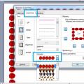 Download and insert a beautiful framework to Word Document
 How to fix clock_watchdog_timeout type "Blue screen" (0x00000101)