Mental Ray GI: interior lighting. Interior lighting system in mental ray 3ds max mental ray lighting
In this tutorial, we will look at the basic principles of setting up lights for interior lighting and creating a global illumination effect in Mental Ray. We will also look at some of the problems that can arise when illuminating a textured scene, and how to solve them.
To complete the lesson, we first need to create a room.
In the projection window Top create a spline Rectangle. Select it and go to the tab Modify command panel. Select a modifier from the list of modifiers Edit Spline. In a scroll Selection click on the button Spline(the red curve is like this) and then in the scroll geometry click on the button outline and in the window Top move the spline outward a bit. Now again from the list of modifiers select extrude and extrude a 3D object of suitable height from the spline. These will be the walls.
Now make a floor and a ceiling from a regular plane.
Next, cut out the window. Create Box. Position it in the wall so that all corners stick out of the wall. Select it and in the category drop-down list geometry tabs Create command bar select line Compound Objects. Click the button Boolean, then, in the rollout that appears, click the button Pick Operand B. Select a wall object in any window. Set the operation type to B-A. The window is ready, just like the stage itself. Although no! Add a couple more beauty objects to the room. It will be something like furniture. Put the ceiling on the walls and everything else with the usual standard gray material.
Position the camera indoors and focus properly.
Point a light source at the window mr Area Spot.

Adjust the light source. When working with photons, the parameter hot spot in a scroll Spotlights Parameters light source. These parameters should be adjusted as precisely as possible to the size of the window through which light enters the room in order to avoid the loss of photons, the maximum number of which depends on the size of your PC's RAM. Since the window is rectangular, then you need to specify the shape Rectangle and adjust the cone to fit the window. To make it easier to change the direction and taper, switch one of the windows to view from the light source. In a scroll Area Light Parameters check the box On and specify the type of scattered light Disc with a scattering radius of 40. Although, you can set a much larger value. I have never seen the sharp outline of a window opening in the shadows when no sunlight enters the window. From this we can draw conclusions. If you want the sun's rays to fall through the window in your scene, then setting blurry shadows will be a big mistake. Another situation is when the light of heaven.
With the creation of the scene like everything. Submit the scene for rendering. Dark isn't it? It's time to deal with global illumination in Mental Ray. Opening the window Render Scene, select as a visualizer mental ray. Go to tab Indirect illumination and in the scroll Caustic and global illumination in the GI block, check the box enable. Render the scene. Virtually nothing has changed. Not without fine tuning.
So, let's start setting up the lighting of our test scene. Set value Maximum Sampling Radius equal 4 . The Radius value is the photon search radius. It is the photon search radius, not the size of the photon! Photons have no size in terms of computer graphics. The absence of the Radius checkbox means that the photon search radius is approximately 110 parts of the scene. Maximum Num value. Photons is the number of samples for calculating the illumination of a point. Meaning Average GI Photons set equal to 10 000 . As you already understood, the GI Photons value determines the number of photons from the light sources, it is this number of photons that is stored in the photon map. The Decay value determines the attenuation with distance, a value of 2 is considered physically correct. The Global Energy Multiplier value is a kind of regulator with which you can control the overall illumination of the scene.

The Trace Depth value sets the level of reflection and refraction of surfaces in the scene. Photon Map - installation of a photon map. Please note that some parameter values in the result may differ depending on the coordinate system. This applies to all parameters that specify dimensions, distances, radius, etc. We consider all values in Inches, not in millimeters or meters, etc.
Render the scene again.

Bright spots of light with a radius of 4 indicate that photons are being generated, that the photon search radius is 4 inches, and the presence of large unlit black areas in the scene indicates that there are not enough photons for this scene. Change the number of photons from 10,000 to 500,000.

Already better, but still dark and there is noise. There are two ways to get rid of the noise and make the lighting more intense. To reduce noise, you can further increase the value of Average GI Photons, but this will lead to an increase in rendering time, and you will not achieve excellent results. The Average GI Photons values are limited by the PC memory and you cannot use very large values. The second option is to increase the photon search radius, which will smooth the picture. But then the secondary shadows will be calculated ugly, which will look completely unnatural. The best option is to adjust these values so that there is no noise and the shadows are normal. Here is a good image.

Here I used Average GI Photons = 1500000, Maximum Sampling Radius = 13, and Global Energy Multiplier = 6500. In fact, the picture is still terrible. Lights appeared due to too high Multiplier value. This can often be seen in galleries, when window sills, window frames and, sometimes, ceilings are highlighted in interior images. It is not right!
Despite the fact that the photon map method gives the most physically accurate results of scene illumination, the number of photons to obtain high-quality illumination with a minimum photon search radius should be too large. Modern PCs and a 32-bit operating system will not allow you to calculate such a number of photons.
The most realistic competent lighting in interiors gives the combined use of photons and Final Gather. What does it represent Final Gather? A hemisphere of unit radius is constructed above the point, and rays are emitted through the surface of the hemisphere in random directions. The more such rays, the more accurate the calculation and the less noise. In practice, the number of rays is the number of samples in Final Gather. For each ray, the intersection with the nearest surface is found. The beam is being processed. There is no further ray tracing. Final Gather ray tracing depth is always set to one. I recommend using only one Final Gather in scenes using HDRI maps in the global environment or exteriors.
And so we turn on Final Gather and set the values as shown. But first return the values Average GI Photons = 10000.

Checkbox preview serves for fast rendering in low quality. Render the scene.

As you can see, there is noise, but not the same as when Final Gather is disabled. Just increase the value Average GI Photons before 200000 and samples in Final Gather with 50 on the 500 , and get a very acceptable picture.

Apply textures. I used standard materials and Max's bitmaps (*.jpg). Render the scene again.

Not a very pleasant sight? Here! Now is the time to talk about the problems that can arise when using Mental Ray GI. As you have already noticed, the scene has a rather strong color transfer from the walls and floor to the ceiling, and indeed to each other. This effect is called . You can deal with this in different ways. For example, controlling color bleeding with photon shaders. But I think the best option is the following. We calculate the photon map and Final Gather in the scene with gray material, as in Figure 9, and save it to a file. Next, we assign the necessary materials to the scene objects and render by loading photons and Final Gather from the file. To be honest, I don't understand why the developers didn't make the color bleeding option like in finalRender, for example.
Let's finish the job. Here is a picture rendered in this way.

For the sake of example, I threw a couple of models of chairs with a carpet and one wall into the scene. I am not an interior designer and this is not a competitive entry, so please do not criticize me for such an incomprehensible attempt at arranging furniture.

A good picture without glare on the window and with uniform illumination and with only one light source. Some might argue that the stage is a bit dark. Stop! And where did you see in reality a well-lit room through such a small window? Do not overdo it with the intensity of light. This is where the highlights appear, and the scene looks unrealistic. A well-lit scene is when it is not bright and without highlights, when all objects and angles in the camera's field of view are clearly distinguishable. To correctly illuminate the scene, use the SkyLight light source.
Finally, I want to give some tips that will help you avoid mistakes in your work with Mental Ray.
1. Never make walls, floors and ceilings with zero thickness! Mental Ray will simply ignore the rotated wall normals and let light into the room as if it were open space. This is also true for other renderers.
2. Use the SkyLight light source for illumination. To add light, realism and highlight the places of window openings that are in the shadow area, SkyLight is best suited. In large interiors with many windows, instead of skylight in window openings, you can use a photometric light source - TargetArea.
3. I recommend using only "native" materials in all external renderers. This applies to a lesser extent to Mental Ray because both standard and ray tracer and architectural materials work quite well in Mental Ray. But, despite this, only the use of "native" materials, which include DGS material, mental ray, Glass (physics_phen) and Lume shaders, gives the most physically accurate correct results. When using (in interior scenes using photon maps) a mental ray material in the Photon slot, you must definitely use a photon shader. When used in the Surface slot - DGS materiala, in the Photon slot it is better to use DGS material Photon. When using Lume shaders in the Surface slot, for example, Metal(lume) in the Photon slot, it is better to use Photon Basic.
4. Photon rendering, Final Gather, and rendering progress can be monitored visually by enabling the Mental Ray Message Window.
5. Adjust the lighting in the scene by assigning a gray material to all objects. Remember that textures and materials tend to hide GI imperfections. And only after you find the optimal GI settings in the scene, assign materials to objects, adjusting the materials to the lighting, and not vice versa. Remember also that in Mental Ray photon shaders have a direct effect on the lighting in the scene, and if you want them not to affect the overall lighting set up in the scene with gray material, set the photon shaders to the same parameters that they had when setting up lighting in a scene. Now let's talk about radii in Final Gather. Max Radius is the distance between points for which GI (Global Illumination) is calculated. The smaller the distance between the points, the more accurate the calculation and the more time it will take. Min Radius is the distance used in the interpolations and extrapolations of the illumination of intermediate points. In practice, to get normal quality GI Min Radius should be 10 times less than Max Radius. Increasing the values of the radii leads to a decrease in the quality of the secondary shadows, a decrease leads to a more accurate calculation of GI and, as a result, an increase in the rendering time. The smaller the radii, the more samples you have to put in Final Gather. The number of samples required for smoothing, with the above values of the radii ranges from 500 to 3000 depending on the scene. The bigger, the better. But do not get carried away by increasing this value, as the rendering time will increase greatly.
This is my first lesson, so please be gentle.
For example, let's take a simple interior object - a bathroom.
I will not write anything about modeling - we will assume that everything is ready.
Scene
(For 3ds max 2010 and above)


In terms of materials, everything is also very simple here.
All chrome is ProMaterial: Metall (Chrome Polished).
Ceramic - ProMaterial: Ceramic. Glass - ProMaterial: Solid Glass.
Stretch glossy ceiling material:

The most difficult material is tile.
Here are the parameters of the black tile (the rest are done in exactly the same way):

Texture maps in the archive.
The main part is the lighting setup.
Its main feature is that it is a closed part of the apartment, illuminated only by artificial light.
In this case, from lightingappliances we have several (1) halogen lamps on the ceiling (they make up the main lighting) and one discharge lamp (2) above the mirror
(illumination of the mirror area).

Now let's move away from talking about the bathroom a little and remember a little physics.
From a high school physics course, you should know that, strictly speaking, a phenomenon such as “color” does not exist in nature.
This is just a feature of the eye's perception of a rather small piece from the line of electromagnetic radiation.
This piece is called the spectrum of visible radiation (or something like that).
Moreover, the eye perceives the longest waves from this spectrum as red colors, and the shortest,
like purple (remember - every hunter wants to know where the pheasant is sitting).
Waves that are longer than "red" are called infrared (or even thermal radiation).
Waves that are shorter than “violet” are ultraviolet (and then X-rays, etc.).

There is a connection between body temperature and its electromagnetic radiation.
Everyone knows that if you glow some object strong enough, it begins to glow.
Those. it begins to radiate first in the infrared, and then in the visible spectrum.
And the stronger the heating, the shorter the radiation length will be. Everyone saw how a piece of metal is heated to red in the fire.
Theoretically, if the same piece of metal is heated further, it will begin to turn from red to orange,

You ask why I mentioned this? And then, so that you understand that the “color” of light is a very conditional concept.
And this is of great importance if you use Mental Ray for visualization and want to operate with real values in the development of your projects.
The thing is that for photometric light sources, in addition to the glow power and various shadow tracing settings, you can adjust the so-called glow temperature.
This is a kind of conditional scale showing how warm (i.e. closer to the red spectrum) or cold (i.e. closer to the blue spectrum) the radiation from it will be.
By the way, most lamp manufacturers indicate this temperature in their product data.
For example, the glow temperature of incandescent lamps is about 2800K.
For halogen lamps, this temperature is about 3000K. For gas-discharge lamps, the spread is quite large from 4000-8000K.
It’s clearer, but still, where is the connection with Mental Ray and our bathroom?
Everything becomes clear when we go to the Environment tab in the Rendering menu (press the number 8 on the keyboard)
and set the Exposure Control rollout to mr Photographic Exposure Control.

Looking closely at the parameters inside, we notice the Image Control section there.
And in it we see the Whitepoint line and the temperature value in Kelvin.
Now we understand the connection between Mental Ray and the physical part described above.
For those who are in the tank, I explain - Whitepoint is the value of the temperature of the light taken as white.
If some IC has a light temperature less than this value, then the color of its radiation moves towards red (the greater the difference, the redder the light).
If the temperature of the light is greater than this value, then the color of the radiation moves towards blue (the greater the difference, the more blue the light).

Now that we have dealt with this, we return to our bathroom. As we said, our main lighting is halogen lamps on the ceiling.
We conscientiously model lamps (or less conscientiously take somewhere else).
Looking at the catalog, we see that these fixtures are equipped with halogen lamps with a power of 50W (or about 65 cd).
We climb again on the Internet and find that the glow temperature of these lamps is 3100K.
We create photometric light sources for them (spherical for simplicity) and set the power to 65cd and the temperature to 3100K (or you can use one of the presets, which is very convenient for Max).
You can of course twist the color of light sources using Filter Color, but these are not our methods.
Although sometimes they have to be used to create colored lamps.
We do the same with the IC for the lamp above the mirror. We create a cylindrical photometric and
We set its power to 32cd and choose from Fluorescent (Daylight) temperature presets so as not to suffer with searches.


We will not configure anything else for the time being - it will do for previews.
Go to Rendering -> Environmet again and in the Exposure Control rollout click on Render Preview.
What do we see? A dark window with an indistinct yellow picture... ugh...
No problem! By turning the Exposure Value, we achieve that the picture becomes quite bright.

We see that strong light has appeared in the field of IP. To get rid of them, you need to twist the Highlights (Burn) value.
I usually leave the value around 0.05 - 0.025, but this is a matter of taste.
You can also rotate the Midtones and Shadows to make the picture more contrast.
And also add a little Color Saturation to make the colors more juicy.
Well, we have achieved the desired brightness and removed the highlights, but the picture is still YELLOW!
This is because the main light we have is given by halogens on the ceiling.
And they shine with a temperature of 3100K, as we set in the settings.
In the Whitepoint line, we have a value of 6500K (the default value).
This means that relatively white, the color that our halogen lamps give, is shifted towards red.
No problem, change the value of Whitepoint to 2100K - i.e. we eliminate this difference and bring the color of the radiation from the lamps to absolutely white.
We see that the picture has changed and the lamp above the mirror has become slightly bluish - the temperature of its light is more than 3100K, which means that its light has shifted towards blue.
In principle, one could calm down on this - the bathroom no longer looks yellow. But it has become rather faded - the light from the lamps is too sterile white.
Personally, I don’t really like it ... we will revive! To "revive" it, we simulate a flash.
I’ll make a reservation right away, I have never been professionally engaged in photography in my life and all my experience in this area is limited to amateur pictures on digital cameras.
But, as they say, what are they rich with ... So we will imitate a soap dish.
If you've ever photographed in a room with artificial light, you've probably noticed
that the flash creates a fill white light against which an incandescent or halogen lamp shines bright orange.
This is exactly the effect we will try to recreate.
Create a photometric and select a rectangle as the shape. Its dimensions affect the blurring of the shadows that the flash will give.
Well, since we are imitating a “soap dish”, then the dimensions can be made small - 20x40mm is enough.
In addition, we need this disk to shine only in one direction - forward.
Therefore, in the Light Distribution (Type) rollout, we will select Uniform Diffuse.
We will make its power 1500cd, and set the temperature to 6600K.
This is best done with the Align tool.

Again we go to Rndering -> Environment, render a preview and set Whitepoint to 6500K - the light from the halogens again shifts to warm orange colors,
and the flash will flood the scene with cold white light.
Now I like it - you can see that the halogens shine with yellow light, and in general the picture has become more saturated and lively.
Although the last picture is slightly overexposed. It doesn't matter - we slightly reduce the Exposure Value in the exposure settings...
That's it - you can make final settings for the render quality and read the final image.
You can also play with Glare to get nice highlights around the light fixtures and around the lamp above the mirror.
Here are the Glare settings that I used in this work:

A little about the render settings.
What I really like about Mental Ray is that most scenes can be easily rendered with default settings.
Below I marked with a red marker all the settings that I changed:

And no dancing with tambourines :)
I don’t think it’s necessary to describe each parameter in detail - it’s better to read about this in the lessons of Alex Kras (many thanks to him for his efforts).
In general, this is all. And finally, my final render without post-processing.
Exkaryon.ru → Lessons → 3D Graphics → 3ds max → Mental Ray GI: interior lighting
In this tutorial, we will cover the basic principles of setting up lights for interior lighting and creating a global illumination effect in mental ray . We will also look at some of the problems that can arise when illuminating a textured scene, and how to solve them.
To complete the lesson, we first need to create a room.
Top viewport create a spline Rectangle . Select it and go to the tab Modify command panel. Select a modifier from the list of modifiers EditSpline. In the Selection scroll click on the button Spline (the red curve is like this) and then in the scroll geometry click on the button Outline and Top window move the spline outward a bit. Now again from the list of modifiers select extrude and extrude a 3D object of suitable height from the spline. These will be the walls.
Now make a floor and a ceiling from a regular plane.
Next, cut out the window. Create Box . Position it in the wall so that all corners stick out of the wall. Select it and in the category drop-down list Geometry tab Create command bar select line Compound Objects . Click the button Boolean , then, in the rollout that appears, click the button Pick Operand B . Select a wall object in any window. Set the operation type to B-A. The window is ready, just like the stage itself. Although no! Add a couple more beauty objects to the room. It will be something like furniture. Put the ceiling on the walls and everything else with the usual standard gray material.
Position the camera indoors and focus properly.
Point a light source at the window mr Area Spot .
Adjust the light source. When working with photons, the parameter Hotspot in the Spotlights Parameters rollout light source. These parameters should be adjusted as precisely as possible to the size of the window through which light enters the room in order to avoid the loss of photons, the maximum number of which depends on the size of your PC's RAM. Since the window is rectangular, then you need to specify the shape Rectangle and adjust the cone to fit the window. To make it easier to change the direction and taper, switch one of the windows to view from the light source. In a scroll Area Light Parameters check the box On and specify the type of scattered light Disc with a scattering radius of 40. Although, you can set a much larger value. I have never seen the sharp outline of a window opening in the shadows when no sunlight enters the window. From this we can draw conclusions. If you want the sun's rays to fall through the window in your scene, then setting blurry shadows will be a big mistake. Another situation is when the light of heaven.
With the creation of the scene like everything. Submit the scene for rendering. Dark isn't it? It's time to deal with global illumination in Mental Ray. Opening the window Render Scene , select as a visualizer mental ray . Go to tab Indirect illumination and rollout Caustic and global illuminationin the GI block, check the box enable . Render the scene. Virtually nothing has changed. Not without fine tuning.
So, let's start setting up the lighting of our test scene. Set value Maximum Sampling Radius equal to 4 . The Radius value is the photon search radius. It is the photon search radius, not the size of the photon! Photons have no size in terms of computer graphics. The absence of the Radius checkbox means that the photon search radius is approximately 110 parts of the scene. Maximum Num value. Photons is the number of samples to calculate the illumination of a point. Meaning Average GI Photons set equal to 10 000 . As you already understood, the GI Photons value determines the number of photons from the light sources, it is this number of photons that is stored in the photon map. The Decay value determines the attenuation with distance, a value of 2 is considered physically correct. The Global Energy Multiplier value is a kind of regulator with which you can control the overall illumination of the scene.
The Trace Depth value sets the level of reflection and refraction of surfaces in the scene. Photon Map installation of a photon map. Please note that some parameter values in the result may differ depending on the coordinate system. This applies to all parameters that specify dimensions, distances, radius, etc. We consider all values in Inches, not in millimeters or meters, etc.
Render the scene again.
Bright spots of light with a radius of 4 indicate that photons are being generated, that the photon search radius is 4 inches, and the presence of large unlit black areas in the scene indicates that there are not enough photons for this scene. Change the number of photons from 10,000 to 500,000.
Already better, but still dark and there is noise. There are two ways to get rid of the noise and make the lighting more intense. To reduce noise, you can further increase the value of Average GI Photons, but this will lead to an increase in rendering time, and you will not achieve excellent results. The Average GI Photons values are limited by the PC memory and you cannot use very large values. The second option is to increase the photon search radius, which will smooth the picture. But then the secondary shadows will be calculated ugly, which will look completely unnatural. The best option is to adjust these values so that there is no noise and the shadows are normal. Here is a good image.
Here I have used the values Average GI Photons = 1500000, Maximum Sampling Radius = 13, a Global Energy Multiplier = 6500.In fact, the picture is still terrible. Lights appeared due to too high Multiplier value. This can often be seen in galleries, when window sills, window frames and, sometimes, ceilings are highlighted in interior images. It is not right!
Despite the fact that the photon map method gives the most physically accurate results of scene illumination, the number of photons to obtain high-quality illumination with a minimum photon search radius should be too large. Modern PCs and a 32-bit operating system will not allow you to calculate such a number of photons.
The most realistic competent lighting in interiors gives the combined use of photons and Final Gather . What does it represent Final Gather ? A hemisphere of unit radius is constructed above the point, and rays are emitted through the surface of the hemisphere in random directions. The more such rays, the more accurate the calculation and the less noise. In practice, the number of rays is the number of samples in Final Gather . For each ray, the intersection with the nearest surface is found. The beam is being processed. There is no further ray tracing. Final Gather ray tracing depth is always set to one. I recommend using only one Final Gather in scenes using HDRI maps in the global environment or exteriors.
And so turn on Final Gather and set the values as shown. But first return the values Average GI Photons = 10000.
Preview checkbox serves for fast rendering in low quality. Render the scene.
As you can see, there is noise, but not the same as when Final Gather is disabled. Just increase the value Average GI Photons to 200000 and Samples in Final Gather from 50 to 500 , and get a very acceptable picture.
Apply textures. I used standard materials and Max's bitmaps (*.jpg). Render the scene again.
Not a very pleasant sight? Here! Now is the time to talk about the problems that can arise when using Mental Ray GI. As you have already noticed, the scene has a rather strong color transfer from the walls and floor to the ceiling, and indeed to each other. This effect is called color bleeding . You can deal with this in different ways. For example, controlling color bleeding with photon shaders. But I think the best option is the following. We calculate the photon map and Final Gather in the scene with gray material, as in Figure 9, and save it to a file. Next, we assign the necessary materials to the scene objects and render by loading photons and Final Gather from the file. To be honest, I don't understand why the developers didn't make the color bleeding option like in finalRender, for example.
Let's finish the job. Here is a picture rendered in this way.
For the sake of example, I threw a couple of models of chairs with a carpet and one wall into the scene. I am not an interior designer and this is not a competitive entry, so please do not criticize me for such an incomprehensible attempt at arranging furniture.
A good picture without glare on the window and with uniform illumination and with only one light source. Some might argue that the stage is a bit dark. Stop! And where did you see in reality a well-lit room through such a small window? Do not overdo it with the intensity of light. This is where the highlights appear, and the scene looks unrealistic. A well-lit scene is when it is not bright and without highlights, when all objects and angles in the camera's field of view are clearly distinguishable. To correctly illuminate the scene, use the SkyLight light source.
Finally, I want to give some tips that will help you avoid mistakes in your work with Mental Ray.
1. Never make walls, floors and ceilings with zero thickness! Mental Ray will simply ignore the rotated wall normals and let light into the room as if it were open space. This is also true for other renderers.
2. Use the SkyLight light source for illumination. To add light, realism and highlight the places of window openings that are in the shadow area, SkyLight is best suited. In large interiors with many windows, instead of skylight in window openings, you can use a photometric light source TargetArea.
3. I recommend using only "native" materials in all external renderers. This applies to a lesser extent to Mental Ray because both standard and ray tracer and architectural materials work quite well in Mental Ray. But, despite this, only the use of "native" materials, which include DGS material, mental ray, Glass (physics_phen) and Lume shaders, gives the most physically accurate correct results. When using (in interior scenes using photon maps) a mental ray material in the Photon slot, you must definitely use a photon shader. When used in the Surface slot - DGS materiala, in the Photon slot it is better to use DGS material Photon. When using Lume shaders in the Surface slot, for example, Metal(lume) in the Photon slot, it is better to use Photon Basic.
4. Photon rendering, Final Gather, and rendering progress can be monitored visually by enabling the Mental Ray Message Window.
5. Adjust the lighting in the scene by assigning a gray material to all objects. Remember that textures and materials tend to hide GI imperfections. And only after you find the optimal GI settings in the scene, assign materials to objects, adjusting the materials to the lighting, and not vice versa. Remember also that in Mental Ray photon shaders have a direct effect on the lighting in the scene, and if you want them not to affect the overall lighting set up in the scene with gray material, set the photon shaders to the same parameters that they had when setting up lighting in a scene. Now let's talk about radii in Final Gather. Max Radius is the distance between points for which GI (Global Illumination) is calculated. The smaller the distance between the points, the more accurate the calculation and the more time it will take. Min Radius is the distance used in interpolations and extrapolations of illumination of intermediate points. In practice, to get normal quality GI Min Radius should be 10 times less than Max Radius. Increasing the radius values leads to a decrease in the quality of the secondary shadows, a decrease in leads to a more accurate rendering of GI and, as a result, an increase in rendering time. The smaller the radii, the more samples you have to put in Final Gather. The number of samples required for smoothing, with the above values of the radii ranges from 500 to 3000 depending on the scene. The bigger, the better. But do not get carried away by increasing this value, as the rendering time will increase greatly.
With us you found Creating gems using mental ray in 3d max .
Do not miss the comments on the lessonCreating gems using mental ray in 3d max.
This material is provided by the site. School-3d.ru for informational purposes only. The administration is not responsible for its content.
I want to offer
tutorial on creating gems in 3d Max, using the mental ray render and an additional shader to it prism_photon. Not so long ago, I set myself such a goal and searched for a long time how to get the right dispersion effect. The lesson is designed for novice users who have recently met Max, each step is described in detail. The version of 3D Max from 9 and higher is used (for 2009 you will have to look for certain settings yourself, there is a slightly different menu nesting), an additional shader is also used, which is freely distributed and can be downloaded for free and without registration here .
Installation instructions are attached in the same place in the archive in the folder for Max.
So, let's begin:
We launched the program, at the beginning you need to select the type of render (otherwise the materials we need will be closed):
In the main menu "Rendering" - "Render ..." or the "F10" button, in the scroll we go down to the "Assign Render" tab, expand it and press the render list button. From the proposed list, select "mental ray Render" and click "OK":
Now let's create a simple scene for testing our material, we will not immediately put a complex-faceted stone, since it will be difficult to understand reflections and refractions on a large number of faces. Let it be an ordinary pyramid (as a child, they indulged in such, letting rainbow reflections on the walls).
We make a pyramid with a base size of 6 cm and a height of 4 cm.
You can, in principle, use other units of measurement (whoever is used to it), but personally it is more convenient for me to use the metric system. Units of measurement are selected in: the main menu "Customize" - "Units Setup ..." and select the menu you need:
So we create a pyramid: In the command panel, select standard primitives and from the proposed pyramid:
to give a more realistic look, we will chamfer the faces of the pyramid, for this it is necessary to convert the primitive into an editable mesh. This is done by right-clicking (RM) on the created pyramid and selecting the option - convert to editable mesh (mesh):
a scroll of properties and actions for the mesh will open in the command panel, we need to select the edges. Press the "Edge" button and select all the edges of the pyramid (you can simply hold the left mouse button (LM) to select the entire field above the pyramid in any viewport) and without removing the selection in the "Edit Geometry" rollout, find the field next to the "Chamfer" button and set there 0.1 cm and press the "Chamfer" button. Everything, the chamfer from the ribs by 1mm is removed:
Now let's create a plane on which the pyramid and two light sources will stand:
In the command panel, select standard primitives and from the proposed "Plane", the dimensions can be set to 100 by 100cm and placed under the base of the pyramid. Next is a light source that will simply illuminate the scene. For this fit "Omni" - an omnidirectional light source. In the command panel, select the light sources and from the proposed - "Omni":
set it high above the pyramid so that the whole scene is illuminated. Next, you need to edit some of its properties. With our "Omni" selected, click on the "Modify" tab on the command bar, and fix the "Multiplier" value to 0.5, thereby reducing the intensity of the light by half.
next, you need to exclude this source from rendering the caustics effect and indirect lighting (at this stage, this will only interfere and delay the process of rendering the scene). point of automatic calculation (just in case, checking that there is no checkbox in the manual control of the calculation):
So, with "Omni" finished. Now we need to create a directional light source that will illuminate the pyramid and we will observe the propagation of the rays of which. In the command panel, from the light sources tab, select “Target Direct”, which gives a direct directional light, set the beam diameter to about 1 cm, and also reduce the beam decay (attenuation) field as much as possible. (the program will edit the beam diameter a little, but for us this is not essential)
ATTENTION! after creation, go to the properties of the light source - the “Modify” tab (as well as for “Omni”) and control the Multiplier parameters, it should be equal to 1.0 and in the “mental ray Indirect illum” rollout, check the automatic calculation of caustics (depending on Max settings when creating the next light source, similar properties are transferred from the previously created one).
All objects in the scene are created, it remains to arrange them correctly. The pyramid must be placed on the edge, not on the base, and a directional light source should be directed to one of the faces. Using the rotate and move buttons, position the pyramid and the light source as we need (for a directional light source, the target and the source itself move separately, if you need to move them at the same time, select them with LM while holding down the "Ctrl" key). In the end, the scene should look something like this:
The last step is to tell the renderer that for the pyramid we need to calculate the caustic effect (the passage of rays in transparent materials) and enable this effect for rendering by the renderer.
Select our pyramid and click on it RM, in the menu that appears, select the object properties item:
on the properties form, look for the “mental ray” tab and check the box Generate caustics:
Now for rendering: Call the render window "F10", go to the "Indirect Illumination" tab, "caustic and GI" rollout and check the box: Caustic-Enable:
The whole scene is prepared, if we render now, we will get an error in calculating the caustics, since the default material of the prism does not imply this effect. Now let's move on to the most important part - creating materials.
Let's create a material for transparent, non-colored minerals (diamond, rock crystal, topaz….)
A little theory:
The main differences between transparent, colorless materials are the different refractive index and dispersion value. There are also less characteristic optical features (from our point of view) double refractive index and effects caused by the structure of the mineral, but at this stage we do not need them.
Refraction is the deflection of a beam of light at the boundary of two media, caused by the difference in the speed of light in these media.
Dispersion The decomposition of white light into its component colors due to the difference in the speed of light, for each wavelength of the spectrum, in materials of different densities.
Here is a table of coefficients for the most common minerals that exist in a colorless version:
* calcite has a double refraction (details below).
Diamond has the highest coffee. dispersion among natural materials, there are artificial materials kof. more than a diamond.
So let's create a material using rock crystal as an example:
In the material editor (called by the “M” button) or (“Rendering” - “Material Editor”), select one of the free materials (balls) and get a material for it (Get Material button), in the browser that opens, select the “mental ray” material. After that, for convenience, we rename the material with our designation Rock crystal. (if you are just starting to work in Max, it is advisable to accustom yourself to giving your own names to all created objects, materials and maps - it will be easier to navigate in large scenes)
we have an “empty material” that has no shader assigned to it. Let's start with the surface. Let's assign the lume glass shader "Glass (lume)" in the "Surface" item:
Now we need to copy the assigned shader to the next shadow slot. Of course, you can select it from the browser in the same way, but it is more convenient and practical to copy it from the assigned one, making them dependent. We return through the nested list of materials one level up open the list of levels and activate our Rock Crystal.
We click RM on the assigned shader for Surface and select copy from the menu, then also RM on the shadow shader slot and specify Paste(instance):
we got two property maps with dependent parameters changing the settings of one, the second one automatically changes.
Let's return to the assigned shader glass (lume) - just press the button with the shader, almost all fields are filled with the values we need:
surface material and diffuse reflection white, reflection and transparency full (unit equals 100%)
but we will change the Index Of Refraction (coff. Refraction) to 1,544 let it be like in the table and if you are modeling another mineral, then its index should be there.
We will not touch the rest of the parameters for now.
We return to the Rock Crystal material and assign a shader to calculate caustic photons:
Click on the button next to Photon and select the added prism_photon shader in the browser:
The first two parameters ior_min and ior_max must differ by the amount of dispersion in our case for crystal by 0.013. that is, the minimum value of ior_min is equal to koff. refraction, and ior_max = ior_min + coffee. dispersion.
Next comes coffee. constituent colors, it is more difficult with them. Firstly, the colors are not represented by the RGB palette, but by something similar to CMYK. And secondly, the value of these coffees. is taken into account incorrectly. If you look at the shader listing (shaders are written in C++), you can see that the weight fractions of colors can be from 0 (no color) to 1 (full color), and the values between them in 0.2 increments, but then that's all is recalculated with the addition of different parameters and as a result it is not possible to completely remove some component (but it would be convenient for certain non-ferrous minerals), besides for small coffees. variance, some component values can cause a render error.
As a result, if you need to correct the spectrum for, for example, a pale yellow mineral towards yellow put coffee. 1,0,0, but for a saturated solid color we have coffee. we can’t even set huge negative values of L. But our material is transparent and not colored, so we leave 1,1,1.
Everything, we have the material ready, you can apply it to the pyramid (you can simply drag the ball with the material onto the pyramid with the mouse, but it’s more competent to select the pyramid and press the button in the materials window). If there are many objects on the stage, and all of them have their own names, then it is more convenient to select the one you need, not on the stage (where it can be hidden) but by pressing the "H" key and selecting from the list.
We render the scene (F10 and the Render button at the bottom, or immediately press the Shift + Q combination) while the window that we want to render should be active (yellow \ default \ frame around the window) if the projection window is not selected, then just click on it RM .
What we have:
The blue arrow is the direction of light, the main stream of light (yellow arrow), which was refracted in the prism (the spectrum decomposition is clearly visible at the edges) and several weak streams from reflections inside the pyramid, as well as colored spots from beveled edges. Basically what was required. If you increase the dispersion on the material, then the decomposition into the spectrum will be much stronger.
If you don't have a similar picture, move the light source, perhaps the wrong location. If you still don't get results after that, you need to check whether the pyramid is included in the calculation of caustics, whether caustics is enabled on the renderer, and whether the automatic calculation of effects for the light source is checked, see above.
NOTE: if you look closely at the spot of light emerging from the pyramid, you will notice that the spot is not pure white light, but consists of separate colored dots. At the same time, by increasing the number of photons on the light source, we will not get rid of this and we will not get pure white light. This is explained by the fact that a noise map (for each component) is superimposed on the light spot by the shader, which simulates light interference in the light stream. We now have a pyramid illuminated by a light source with parallel beams, a kind of hypothetical white laser, and as a result, noticeable noise is obtained (look at the spot from the laser pointer, there will also be noise-specs). When the scene is illuminated by other sources (Target Spot, Omni), this effect will be minimized.
We continue to improve the material:
Many minerals, especially precious stones, have a high reflectivity, much greater than that of the glass we use (glass(lume)) and we can no longer increase it on this material (it already costs 1 there).
Therefore, we will create another material mirror, and then we will make a mixture of the resulting ones.
Select a new material in the editor and assign it a material from the main library Arch&Desing:
Let's call it for convenience "reflective" and set the properties of reflection and transparency to the maximum (=1), cof. refraction the one we want for our case:
Let's go down and edit the specular function, increasing the specular values for the light coming in at small angles:
That's all. Applying the material to the pyramid and making a calculation, we will see the following:
Almost all the light was reflected from the first face and edges that's what you need.
Now we make a mixture of two materials. To do this, you need an auxiliary material Blend.
Select the third free material and assign a Blend to it:
In the properties of this material, we see two slots for blending materials and a third slot for a blend mask.
Click the first material and link it to the Rhinestone material. On the right is a button that shows the current material, now it is standard, click it, the browser opens, indicate that we want to take a sample of the material from the editor switch the checkbox from NEW to mtl Editor. And let's specify our material:
After that, Max will ask - do we want to get a copy of the material or a dependent material, we need a dependent one to correct the parameters only for the parent material, and the dependent ones themselves will be corrected.
Now the mask. I use a gradient for the blend mask, you can get uneven blending in it, but now we will use the gradient to blend the materials evenly, in principle, you can use the fall / fade map Falloff. Then you can try different options on your own.
So. Click on the slot with the mask and select the Gradient Ramp map, not forgetting to indicate that we are using a new map, and not taking it from the editor:
On the gradient map, delete the extra (at the moment) key (slider) and by clicking on the extreme ones set the dark gray color:
The closer to white - the more effective the second material (reflective) and vice versa. In this way we can regulate the dominance of one or the other material. Now let's set the proportion of colors for crystal to be from 8 to 12, for diamond, for example, you need in the region of 90-120.
The final touch remains:
If there is one pebble on the stage, in splendid isolation, surrounded by emptiness, then it looks “tasteless” - there is nothing to reflect, nothing to refract, except for the table and light. Therefore, we will add an artificial environment to it (for scenes with a large number of objects, this is not so important in principle, but we have a lonely pyramid).
We take another free material and assign it a Bitmap.
A dialog for opening files with pictures will be offered choose according to your taste. I used a prepared environment map simulating a room.
The map is ready, now let's connect it to the material. Open the Rhinestone material and find the environment shader (Environment), click and connect the Max environment shader:
Now everything is ready. You can save the finished material to the library (button) so that you no longer create it from scratch and take up space in the editor (the entire library can then also be saved to a separate file).
Calculation result:
Now you can make models of faceted stones and use them with the created material.
It should be borne in mind that for different types of precious stones, there are certain cuts designed for coffee. refraction of a certain stone. If a diamond is cut into an emerald shape, then we will not get a beautiful play of light. Almost all forms of cutting have long been calculated and even have their own names. Keep this in mind when creating a stone model.
Now PICKUPS:
For different illuminated objects, you need to adjust the energy of light: the Energy property in the mental ray Indirect Illum tab. of a given light source (not to be confused with the Multiplier property), the greater the energy, the brighter the output beam (and the main initial light remains the same).
Sometimes the light spot from the emerging beam consists of separate circles (this is noticeable from omnidirectional sources) - this indicates a small number of photons in the beam it is necessary to increase their number: the Photon property in the same tab.
Only pure white light sources can be used to get the dispersion effect, otherwise the shader stops working.
Using exact physical parameters does not always give a beautiful picture, sometimes you need to sacrifice physics before art if you want a pebble to play with rainbow colors in your picture overestimate the dispersion. Beauty requires sacrifice.
It remains to briefly dwell on individual features and colored minerals.
On the one hand, you can use glass materials from Max's library for them, fixing only the coffee. refraction:
Ruby, sapphire 1,766
Tourmaline - 1,616
Emerald, beryls 1,570
Aquamarine 1,577.
But on the other hand, these minerals have a huge number of properties characteristic only of them, which is impossible to describe everything within the framework of one lesson.
For example
1. double coffee. refraction, when the beam is split in the mineral into two parts and each part has its own cof. dispersion. This is calcite and some (I don’t remember now) variety of spar. For them, you will have to create a composite material from two coffees mixed with different ones. break and coffee dispersion. You will get something like this:
2. There are minerals with the transparency of not “pure water”, containing either some impurities or with defects in the crystal lattice. This effect is adjusted by changing the parameters Blur transparency, Blur reflection, in the glass material. And the Translucency parameter (translucency) makes the material transparent on one side, this can be useful for a stone that is covered with a special reflective paint from below.
3. There are colored minerals, but nevertheless you can see the effect of dispersion in a certain range of the spectrum. For example, a ruby is a red mineral, but if you look closely at a light spot, from the rays passing through it, you can see areas with a purple shift. something like that:
It is achieved by replacing the photon shader with the Max shader for the dielectric material, and setting its color to purple, then the purple color will dominate on the brightest spots just what you need.
Moreover, the ruby itself begins to emit light under the influence of external sources, try to bring a ring with a ruby into a room lit by the so-called Black Light lamp (used in discos and currency detectors), the ruby will glow quite brightly in pink or purple (depending on the mineral) . This is easily achieved, either to illuminate the stone with an additional source, excluding the rest, not forgetting to turn on GI later, or the Illumination property.
5. There is a so-called pleochroism effect, when the stone changes its color depending on the angle of view, this effect can be achieved by applying a color attenuation map to diffuse reflection.
But by and large, this is not very important and you can use ordinary glass to simulate any stone, adjusting the transparency, color, reflectivity and IOR.
Oh, and lighting it right.
Lastly, I repeat: in order to emphasize the beauty of a stone, it is necessary to greatly overestimate some physical characteristics; in the real world, not all minerals look as impressive as they are drawn and described:
Lesson for beginners in Mental Ray creating and lighting a simple room in 3ds max
In this tutorial, we will start exploring the wonderful renderer built into 3d max - Mental Ray - and create a simple room by setting up the lighting. I'll be using 3ds max 9, but you can follow this tutorial with any version of the program. I've also included a completed 3d max scene file in this tutorial, so you can grab it right away and look at the settings.
Final render with some materials and direct light
Download the room for the Mental Ray lesson: mental-ray-room1.zip
I assume that your level of knowledge is not zero, but a low level of knowledge of 3d max is enough to understand this lesson. This is especially true for those of you who have been using the standard Scanline visualizer for several days or weeks. , but wants to expand his knowledge by learning mental ray. While each step is fully illustrated, remember that you can't get started with 3d max directly from mental ray.
1. Create a box and rotate its normals.
I will start by creating a 200x100x70 box - this will be the base of my room.
Convert it to Editable Poly (Editable Polygon) by right-clicking on it and selecting Editaple Poly.
Select all polygons, and in the Edit Polygons rollout (Polygon Editing) select Flip (Invert).
Create a box with normals inward
2. Make windows and details.
Don't be afraid to deviate a little from what was written in the lesson if you feel confident. I will create one window at the end of the long room. However, you can do ambitious things with the roof by creating a long skylight, adding beams, plants. Oh oh oh! But for myself, and for the sake of newbies who are watching this tutorial right now, I will try to keep everything as simple as possible for now.
Select the polygon at the end of the corridor and apply Inset (Insert), then Extrude (Extrude) it with a negative value. You can resize the window if you like. I selected the bottom polygon of the window sill and moved it slightly up.
Delete this polygon. This is how we will create our window!
Cut out the window in the room
Select the polygon on the floor. Make a small Inset and then extrude it down a bit to form the baseboard. This little stylistic thing always adds a bit of realism to a room! I also took the artistic audacity of lifting the base of the window up a little.
Create the edge of the floor
Now we have a sketch for the room. Save your work. Get yourself into this habit.
3. Switch render to mental ray and create some lights.
We need to enable the mental ray renderer because 3d max uses scanline by default. To open the Render Settings window (Visualization Settings) press F10, and on the tab Common in the Assign Renderer rollout (Assign renderer) and click “…” next to Production (Production) and select the mental ray renderer. For the link in the little pink box in the lower left corner, you can type:
renderers.production = mental_ray_renderer()
Super! Now let's add lights to the scene. On the Create panel (Create) go to group Lights (Lights) and select mr Area Omni . Place it by the window sill in the projection window Perspective (Perspective). Take him out the window.
Lesson on setting up lighting and interior rendering in mental ray 3ds max with mr Sun & Sky
Welcome to our next mental ray 3ds max lighting tutorial! Today I will show you the process of creating a typical office interior scene lighting project. Keep in mind that this is far from the only way to light an interior, and your scene's rendering time can be greatly increased. We'll be using mental ray Sun & Sky for the main lighting, and a few area lights for the hallway. I'll be showing you some general settings as the tutorial progresses, and by the time it's finished, you should have a nicely lit interior scene!
Download the initial scene 3ds max mental_ray_lighting02.zip
Our final render
Please note that in some of these images there is a light leak from above the center of the wall divider. I did not notice this until I finished the lesson, so please forgive me for this mistake. In the scene that I posted for download, this error is corrected. In addition, at the end I replaced the flooring with carpet instead of parquet, so don't be surprised when you run the render and see carpet in the render.
Where the magic begins
We move on. Download the file. There will be no lights in it, but the materials are already set up. I have also included the materials of the coffee maker and the wood. However, you are free to add any other material here! If you want a high quality render, you can add a table to the scene and hang blinds on the windows.
Our render without light
If you do a quick render, you will see that the light is not impressive, but the materials are set up correctly, which is fine for us to start with.
The first thing we need to do is create a daylight system in 3dsmax. Creating renders during the daytime is as easy as two fingers on the pavement, because the light comes mainly from outside. On the Systems tab (Systems) panels Modify (modify) you will see Daylight (Daylight). Create a daylight system by clicking and dragging the compass rose in the viewport, and click to create a light source. When a dialog box appears asking if you want to use Photographic Exposure Control (Photographic exposure control), reply Yes (Yes). Photographic exposure will give good results and is essential for this tutorial. The direction of the light source does not matter. In the Modify panel, click in the group position (Location) by button Manual (Manually), thanks to which you can drag the sun to any place. I recommend choosing a beam angle that reflects light off the floor and wall.
Scene review and setup
Ignore the box you see on the open side of the building. This is a little hack that allows you to see the room's decor through the wall, and at the same time is impenetrable to light. This box is visible when rendered and casts shadows. The Shell modifier has been applied to the remaining walls.
The next step is to set the object type of the sunlight to mr Sun (mr Sun) and mr Sky (mr Sky). I know it may seem like they should already be set by default, but there are times when you need to use IES (Information exchange system). Although our case is not one of them. When you install a daylight system in mental ray Sun and Sky, you are connecting a powerful natural light engine that can make anything look amazing. If a window appears asking if you want to set to background mr sky map (Mr Sky card), answer Yes. This will be a good choice if you don't have anything to put as a background.
Setting up mental ray Sun & Sky
Lesson on rendering diamonds (precious stones) in 3d max + mental ray
They say diamonds are a girl's best friend, but for the guys who render them, they can be their worst nightmare.
One of the reasons for this is the characteristic feature of good diamonds, known in the gemstone business world as "glow" - amazingly beautiful colors.
These colors appear due to the fact that the brilliant is a material with a very high dispersion. This is also due to the fact that, in order to produce brilliants, diamonds are specially "cut" to improve the qualities of "glow" (dispersion) and "brilliance" (the ability to reflect light back to the viewer) as much as possible.
But before we get into actually rendering dispersion, let's first see what it's like to render realistic gems without dispersion.
Setting up the scene to render gems in mental ray
Let's start with a ridiculously simple 3D model of a diamond. I'm bad at modeling in 3ds max, so I just downloaded the classic round brilliant cut brilliant.rar (the cut is no longer round, because that model is no longer available, I provided a similar model for download in FBX format import it into the scene via the File > Import menu), and made this super-complex scene:
First we need to make sure we have gamma correction turned on, because diamonds, like other physical objects, must be rendered linearly.
Without gamma correction not very
Good with gamma correction
Lesson on creating a 3D underwater scene in mental ray
In this tutorial we will create an underwater world scene in 3dsmax , for rendering of which its native renderer is applicable mental ray . Our deep blue sea scene will be flooded with rays of light penetrating the water and filled with air bubbles. Creating underwater scenes is a very difficult task, and I'm not even trying to recreate a physically accurate simulation. Rather, I'll take advantage of my creative freedom and defy some real-world rules to get the look and feel of the scene that I want.
1. mental ray renderer
We will be rendering a 3D underwater scene in mental ray. By default 3ds max uses the renderer Scanline so we need to change it. Make mental ray the current renderer (Rendering > Render Setup > Common > Assign Renderer > Production > mental ray Renderer(Render > Render Setup > General tab > Assign Renderer > Production Quality > mental ray renderer).
2. Basic 3D water geometry
Create a plane (Create > Geometry > Standard Primitives > Plane(Create panel > Geometry > Standard Primitives > Plane) in the projection window Top (Above). Change the plane according to the following options (select it and go to the panel Modify (Change):
Length (Length): 1000
Width (Width): 500
Length Segs (Number of segments in length): 200
Width Segs (Number of segments in width): 200
(We need such a dense mesh for the reason that we will apply the modifier to it Displace (Offset) ).
3ds max water surface with Displace modifier
Add a Displace modifier to the plane (Modify > Modifier List > Object-Space Modifiers > Displace(Modification > List of Modifiers > Object-Space Modifiers > Offset) and apply the following options:
Displacement
Strength (Strength): 17
image
Map: Noise (Map: Noise)
Open Material Editor (Material Editor) (Rendering > Material Editor > Compact Material Editor). Drag the Noise map from the Displace modifier into the Material slot of the Material Editor and select Instance (Instance) when asked. Apply the following settings to the Noise map:
Noise Parameters (Noise parameters)
Noise Type: Turbulence (Noise Type: Turbulence)
Levels: 10
Size: 300
Using HDRI in mental ray | 3dsmax
In this tutorial, there will be no step-by-step explanations on how to create such a scene using HDRI in 3ds max & mental ray . Here is a file with the finished scene, downloading which you can see all the parameters that I used to get the rendering of this image.
Download the 3ds max scene file and all necessary files (including the HDR file and textures) by clicking on the link: hdr_max6tut_emreg.zip
After loading this scene file, you will see something like this. I have already created everything and you do not need to do anything. Just open up the options.
I created skylight (Heavenly light) and chose use scene environment (Use the environment from the scene).
It is not necessary to describe all the details about parameters and materials. You can see them yourself in the proposed scene. Below is just a screenshot of the material I used for the cup and plate.
Please try to study all the materials and understand how they apply.
Below are the parameters of the HDR map used for the environment. Skylight has been set up to use the environment from the scene. Therefore, it will use any file that we choose as an environment.
Now take a look at the mental ray settings used to get the image. Remember that this is just a matter of trial and error. It is very difficult to find the best settings the first time. Thus, we need to start with the minimum settings and gradually increase them until the result makes us happy.
Clay Render in 3D Max and mental ray (gypsum render)
|
This time we will learn the method of "gypsum" rendering Clay Render in 3ds max (and someone already knows all this, just yawns from boredom and goes on about their business on the Internet). This technique has found wide application among tridashniks when you need to show the community or friends-girlfriends your still unfinished model without textures. Everything about everything will take you a couple of minutes. 1. For example, I will take a 3D model of a private multi-storey residential building, but you can use absolutely any. Under the building model, I created a plane (Plane) large enough for the shadows to fall on.
7. This step can be skipped, but let's improve the render quality a bit by getting rid of jagged edges. Open the Render Setup window (F10) and switch to the Renderer tab. In it, set the parameter Samples per pixel (Samples per pixel) to 4 and 4. Also select an anti-aliasing filter Mitchell (According to Mitchell).
|
|
In today's 3DS Max tutorial we will analyze the illumination of a small room (a luxury prison cell) by light passing through a barred window. Such a lighting scenario is quite common, you may have seen it more than once in life (I hope, not sitting in a camera), so the lesson will serve as an excellent example on which you will learn how to put "live" light on your own. What you need to know about lighting
Scene 3D Max
Planning and defining light sources
The bars of the grille will give the shadows that fit the idea, enhancing the sense of depth and realism of the scene.
Global Illumination Global Illumination
5. Let's work on this material. In the Diffuse card slot, the Ambient / Reflective Occlusion card (Ambient / Reflective occlusion).
|
Window lighting basics in mental ray + 3d Max
|
11. Almost done. But the scene is still dark. Fix this by clicking on the Daylight system, Modify tab, and set the value Multiplier (Multiplier) by 3.2.
Rendering settings and general mood of the scene
14. To fix the shadows, click on the Daylight system, go to the Modify tab again and set the following there:
|
Lighting Mental Ray
|
Lighting with Mental Ray This tutorial was written by Mario Malagrino for Florence Design Academy. The first step we will take is to create an environment object (this is similar to the rooms (places) where we will later place our object) The color you have to assign to the environment object should be white like the walls of a photo studio! The material should not have mirror highlights. This way the color of the environment will not affect the color of your product (especially if you are using reflective materials). Of course this is the designer's choice. Let's take the first steps to create an environment. Create a spline like the letter "L". Then choose an angle vertex , click on fillet " in the panel on the right and smooth the corner similar to the one in Figure 1. If you want a smoother corner then put a larger value in the slot opposite the fillet button . Now we need to create the thickness of this wall. At the top select " splines ", so that the inscription turns yellow, and select the splines with the command " outline ", which you can find on the same panel on the right. Drag a bit to the right to create thickness. Now give the spline an "extrude" modifier. (fig.2)
Switch to the hierarchy, click on the " affect pivot only " and move the center of the object to the desired position. After this step is done, on the spline apply the modifier " later " from the list of modifiers. You will see that you have created an object similar to a pipe. In the modifier settings, set a larger value segments to have a smoother shape. degrees set to 180. You should get a result similar to figure 4. (note: before applying the modifier later , you need to disable or remove the modifier extrude) Both of these two objects are really useful. Choose which one to use. Create a teapot on an environment object and create a simple skylight . (Figure 5). For now, you can leave the default multiplier = 1, in skylight settings . To have correct rendering with skylight , you must enable final gather in Mental Ray settings (no final gather , skylight will not work). For the first test, put Final Gather Samples by 40. Now let's make a test visualization. You should get something like Figure 7. skylight NOT capable of creating specular highlights on an object. Specular highlights are VERY important for creating different kinds of materials. Therefore, it is not necessary to use only one skylight in your scenes. It is important to have additional light. If you want very strong specular highlights like car paint material, you should use Mr Omni lights . For this tutorial I will use photometric target area light . This light is softer and produces very good and realistic results. Create target area light similar to the one shown in figure 8. The shadow type MUST be " raytraced shadows ", only this type of shadow will give optimal results with mental ray . Since we now have two lights, we need to decrease the value skylight . Try to put multiplier between 0.4 and 0.7. Do the rendering. You should get a result similar to Figure 9. This is how it is done if the object has no reflections. If you have an object with a reflective material, then you have to do a few more things. If your object has a chrome material, you will get this result (see creating chrome in other tutorials) (Fig. 10). Fig.10 Create a white material, self-illuminated at 100 and apply to these boxes. You will see a big difference between Figure 10 and Figure 12. The reflection of these boxes gives the impression of two light sources, similar to windows or large white panels that are used in the field of professional photography. You may notice that image 10 is slightly darker than image 12. Why is that? Whenever you turn final gather , objects with self illuminated material capable of spreading light. The more self illuminated on an object, the brighter the surface close to that object becomes. That is why image 12 is slightly brighter. Now press CTRL+C and CTRL+V (copy and paste). You will see in the Layers panel that a new layer has been automatically created with only the masked part of the teapot on it (see Figure 14). Now double click the left mouse button on the new layer. Select " OUTER glow " and change the yellow color to white. Then adjust the size. Now you have a glow effect. First of all we have to connect our two layers. Go to section " layer" and select "flatten image" (Figure 15). Fig.15 Fig.16 The last step is very important. Select the eraser tool " and delete the part of the image that should be clear (Figure 18). Set opacity to 60, on the tool " erasertool". Fig.18 Translation that you can say: |
Visualizer Mental Ray 3.3.
Since the sixth version of 3ds max, the mental ray photorealistic renderer has been integrated into the program. This was not an unexpected innovation, since 3ds max's own renderer for rendering scenes has long ceased to meet the requirements of the creators of three-dimensional graphics. From version to version, Discreet developers tried to make changes to the image rendering algorithm, but their efforts were unsuccessful. The proof can be found in the numerous works of 3D graphics designers made using plug-in visualizers Brazil, finalRender Stage-1, V-Ray and etc.
Thus, starting with the sixth version of 3ds max, a radically new approach was taken to the problem of realistic rendering. The choice of the developers of 3ds max 7 fell on the product of Mental Images.
To use mental ray to visualize, you need to run the command Rendering > Render (Render > Render) and in the settings rollout Assign Renderer (Assign a visualizer) click on the button with the image of the ellipsis next to the line Production (Performance). In the list that opens, select mental ray renderer.
Render Scene Dialog Box (Scene Rendering) of the standard renderer contains five tabs: Common (Standard settings), Renderer (Visualizer), Render Elements (Visualization Components), Raytracer (Tracer), Advanced Lighting (Supplementary lighting) (See Fig. 7.1).
Rice. 7.4. View of the Render Scene window after selecting mental ray 3.3 as the current scene renderer
If you select mental ray 3.3 as the current renderer, then the window tabs Render Scene e (Render Scene) will change their name. Instead of Raytracer (tracer) and Advanced Lighting ( Additional lighting) tabs will appear Processing and Indirect Illumination (Indirect lighting) (Fig. 7.4). Region global illumination (General lighting) of the last tab contains settings for caustics and parameters related to the rendering of light scattering.
With the advent of mental ray lights added to 3ds max mr Area Omni (Directional used by renderer mental ray) and mr Area Spot (Omnidirectional used by renderer mental ray ) (Fig. 7.5). These light sources are recommended to be used in scenes for correct rendering by the renderer. However mental ray It renders the illumination of the scene quite well even with standard light sources.
Rice. 7.5. 3ds max 7 standard lights
As a shadow map for a photorealistic renderer, you can use Ray Traced Shadows (Shadows resulting from tracing) and your own shadow map mental ray Shadow Map (Map of shadows mental ray ). In the first case, the rendering will be done by the ray tracer mental ray. Standard shadow map shadow map (Shadow map) when rendered by this renderer shows noticeably worse results, so it is not advisable to use it.
For realistic rendering of mental ray textures, like other external renderers, uses its own material. The Material Editor contains seven new types, indicated by a yellow circle: mental ray, DGS and Glass (Glass), SSS Fast Material (mi), SSS Fast Skin Material (mi), SSS Fast Skin Material+Displace (mi) and SSS Physical Material (mi) (Fig. 7.6). The first type of material mental ray consists of shading type surface (Surface) and nine additional shading methods that define material characteristics.
Material DGS controls the color of scattered rays parameter diffuse (Scattering), flare shape Glossy (Gloss) and the power of reflection Specular (Shine).
Glass type (Glass) allows you to control the basic settings of the material type Glass (Glass).
Rice. 7.6. Materials added by mental ray 3.3 renderer
The remaining four materials, whose names begin with SSS , are intended for scenes in which you want to use the subsurface scattering effect ( Sub-Surface Scattering ). With these materials, you can quickly create a realistic image of the skin and other organic substances.
Please note that you can only see these materials when you select mental ray as your current renderer. . These materials are configured using shading types that are similar to the standard 3ds max 7 procedural maps. The concept of shading type for the renderer mental ray has a slightly different meaning than a procedural map for a standard renderer. Shading type for mental ray determines not only the behavior of the rays reflected from the object, but also the image rendering algorithm itself.
mental ray material has its own set of additional shading types that you can work with in the same way as with standard 3ds max 7 procedural maps. Matenal/Map Browser (Material and map selection window) shading typesmentalraymarked with yellow icons. List of shading types in the windowMaterial/Map Browser(Window for selecting materials and maps) can be different - it all depends on which parameter the type of shading is assigned to.
For example, if you try to assign a shading method as a parameter Contour(contour) materialmental Ray,nine types of shading will be available. If you assign the shading method as a parameterBump(Terrain) you can only see the three types of shading available.
ATTENTION
When you use the default or any other renderer other than mental ray 3.3, renderer shading types are usually shown in the windowmaterial editor(Material Editor) as dark and light spots or not displayed at all. If appliedmental ray 3 3the scene will correctly show and then render most of the standard 3ds max 7 materials and texture maps.
Visualizer mental rayhas a fairly large number of settings and allows you to get pretty good results when rendering (Fig. 7.7).
Rice. 7.7. Image rendered with mental ray 3.3
The mental ray material has the following options:
- creating motion blur and depth of field effects;
- detailed drawing of the displacement map (displacement);
- distributed rendering (distributedRendering);
- use of typesCamerashaders(Camera Shading) to obtainlenseffects(Lens effect) and other effects;
- creating a "drawn", non-photorealistic image using the parameterContourshaders(Outline shading).
An alternative to the standard rendering algorithm, the mental ray 3.3 renderer provides high-speed rendering of reflections and refractions, and also allows you to get a photorealistic image that takes into account the physical properties of light. Like all photorealistic renderers connected to 3ds max 7, mental ray 3.3 uses photon analysis of the scene.
A light source located in a 3D scene emits photons with a certain energy. Getting on the surface of three-dimensional objects, photons bounce off with less energy.
The mental ray 3.3 renderer collects information about the number of photons at each point in space, sums up the energy, and based on this calculates the illumination of the scene. A large number of photons allows you to get the most accurate picture of illumination.
The photon tracing method is used both to create the effect of global illumination and to calculate the effects of reflective and refractive caustics (see above).
Rice. 7.8. Switching to object properties using the context menu
The main problem of rendering global illumination and caustics is the optimization of calculations. There are a large number of ways to optimize the rendering process and speed up the rendering time. For example, in settingsmental ray 3.3you can specify the maximum number of reflections and refractions to be calculated, as well as determine which objects from those present in the scene will be used to generate and receive global illumination and caustics. To specify whether an object will be taken into account when calculating these effects, right-click on it and select the line from the context menuProperties(Properties) (Fig. 7.8).
In the window ObjectProperties(Object properties) go to tabmentalray(Fig. 7.9) and define the properties of the object by checking the necessary checkboxes from the following:
- Generate Caustics(Generate caustics);
- Receive Caustics(Accept caustics);
- Generate Global Illumination(Generate general lighting);
- Receive Global Illumination(Take general lighting).
Rice. 7.9. mental ray tab of the Object Properties dialog box
Lesson taken from RENDER.RU
I continue the theme of lighting in Mental Ray. In this lesson I want to talk about simulating artificial light sources to illuminate rooms. Photometric light sources will be used, which 3D MAX 2009 puts at our disposal. Photometric exposure control will also be considered.
It is assumed that readers of this tutorial are familiar with the tutorial on indirect lighting: posted earlier.
Let's start
When choosing any photometric light source, Max insistently suggests turning on the photometric exposure control, so I will start the lesson by describing this type of exposure.
Exposure control:
After creating a light source according to its physical characteristics (brightness, color, ...), it is understood that lighting the scene with it is the most correct and we only have to globally change the brightness of the image (render) using exposure control.
Photometric exposure control is made in MR by analogy with the operation of a camera.
Answering yes to the warning when first creating the photometric:
we consent to the inclusion of appropriate exposure.
The exposure control menu is accessed from the main menu:

or through the "Environment" item (key 8).

in the mr Photographic Exposure Control rollout, you are prompted to select preset exposure parameters:

for exterior scene (day\night) and interior (day/night) scene, but they are usually very rough and it is still better and more correct to adjust manually:
Those who use cameras know that the main parameters (for lighting) when shooting are film / matrix sensitivity (ISO), aperture and shutter speed (shutter speed). The brightness of the picture depends on the setting of these parameters.
For example, pictures that include a table lamp with a light bulb with the following settings:
that is, the brightness is 370 lm, and the color of the light flux is 4500-5000K (halogen)
Due to the setting of different shutter speeds, the brightness of the picture is different. Similarly, in MR, by setting different exposure parameters, we change the brightness of the render image, without changing the parameters of the light sources .
For example, I made a very simple scene where there is a light source with the same physical parameters as in the photo, and only the shutter speed in the exposure changes:
|
|
|
|
|
|


Options:
Shutter Speed- this is the shutter speed or shutter speed, the value by which 1 second is divided is set - the larger the set value, the darker the picture
Aperture- aperture size - the larger, the brighter the picture
film speed- film sensitivity - the higher, the more sensitive the film to light and the brighter the picture.
In 3d MAX, it is not necessary to edit all three parameters, a parameter is created based on them exposure value which is used by the renderer, so it is enough to either set EV, or, as I usually do, set only the shutter speed.
Below exposure settings are image processing options, similar to digital cameras or film filters. - gamma adapted to the type of light sources.
Actually, there is nothing complicated in using the exposure, the main thing to remember is that you should not change the intensity of the light sources, thereby introducing an imbalance in the scene - just adjust the exposure for a darker / lighter image on the render.
Now, in fact, the light sources
When creating an artificial light source, the editor divides them into targeted and free ones:

no matter what source is created, you can make it either targeted or free at any time by checking the target checkbox in the main source parameters tab.

From my own experience, I can advise you to first create a targeted source, for the convenience of placing it on the stage, and then turn off the target, so that later there are no problems with the orientation of the emitter in sources other than point sources.
For the correct calculation of shadows, it is proposed to use traced shadows "Ray Traced Shadows", which are created taking into account the characteristics of the material of the object.

Depending on the requirements of the scene, or the effects being created, you can use Shadow Maps, which are calculated faster, but do not take into account all the characteristics of the materials.
Shadow examples:
Traced shadows:

shadow map with default settings:

as you can see, the transparent material is not taken into account, the shadows are created based on the mesh of the object. The quality of the shadow depends on the quality of the shadow map creation and is configured in the "Shadow Map Params" rollout of the light source settings. For example, by increasing the map size or sampling quality, you can achieve sharper shadows.


Since the lesson is aimed at creating artificial light sources for the interior, I will not dwell on creating a shadow map, since in interiors (in my opinion) it is more relevant to use traced shadows.
As for traced shadows - sometimes when using Thin Geometry, Glass (lume) glass, some artifacts appear on the object, in the form of separate spots (look at the first figure with traced shadows - the right cube has spots on the inner shadow). Improving the sampling parameters in the render is useless here. You need to enable the two-sided shadows option in the light source settings:


Photometric Web- a light source whose configuration and intensity is calculated on the basis of the "photometric web" most accurately conveys the parameters of light and saves a lot of time when creating scene illumination.
Spotlight- a light source of the "spotlight" type is usually used for global illumination of the scene, in interior solutions its use is irrelevant (again, my opinion), except for imitation of projectors or special effects.
Uniform Diffuse- a light source illuminating in the direction from the emitter to the target.
Uniform Spherical- a light source that illuminates in all directions from the emitter.
Uniform Diffuse and Uniform Spherical
The settings of these types of sources are identical, with their help you can simulate almost any light source - fluorescent lamps, light bulbs and ceiling panels:
In the settings, you are prompted to select the type of emitter:

and if the emitter is different from the point (Point) then it will be possible to include it in the rendering process

Consider some of the nuances of creating specific light sources:
Daylight lamps:
When creating a fluorescent lamp, its intensity, based on the entered data, will be calculated as from a conventional light source, but for fluorescent lamps (especially older models), the distribution of light will be visually slightly different. Due to the fact that the luminescent layer is irradiated with ions with a certain frequency (and in old lamps with a frequency of 50 hertz) and due to the peculiarities of our vision, the light intensity will decrease faster than from a source with a filament (this applies only to the visible image, physically , over a period of time, light attenuation is quite normal).
So let's increase the damping:
Pre-render with normal settings:

set the attenuation to 50% (I didn’t find any information about the exact values, but on the example of the Soviet LB’eshka, testing showed just that)

It would seem that you can simply reduce the brightness at the source, but when using ready-made source profiles from IES, it is more convenient and the calculations are more correct:

Incandescent lamps:
Incandescent lamps also have an additional effect of changing light with distance, but it is expressed in the shift of the source spectrum to the red region:
To enable this effect, you just need to check the box:

for example, I slightly increased the attenuation value so that there is a more visual effect:
pre-render with light source at 4000K:

and attenuation is on:

examples of scenes using these source types
in this scene, emitters are not involved in the rendering process, but highlights on surfaces still correctly take into account the presence of sources:

on the second scene of the object of the "public MeJo" type, the sources are visualized and imitate the surface of the lamps:

Photometric Web
In the real world, the flow of light from lamps is extremely rarely uniform, due to the fact that the lamp bulb itself is a lens, and, as a rule, reflectors and additional optics in the lamp change the flow.
For example, here is a photo of a random light source that I came across at lunch:

to create such a picture of the light flux, you need additional constructions near the source, or draw a map for the "Projector Map", which requires additional time and distracts from the creative process.
They will simplify the procedure for creating light sources, using the type Photometric Web:
When this type is selected in the source settings, a scroll will appear to select the settings map:

by clicking on the file selection button, a dialog for selecting a map will open:

the "IES information" section presents a diagram of the propagation of light on the "web" and information about the light source.
IES files can be downloaded from the net, as a rule, lighting equipment manufacturers provide such maps, or interior design archives can be found. There are also IES generators with which you can create your own sources.
After applying the IES map, the light source icon takes on the source configuration:
in the Photometric Web settings there are three-axis rotation options, these settings are relevant when the source is other than a point source. If the source, for example, is linear (Line), and the map has a complex configuration, then the method of positioning the map becomes relevant:

in the figure at the right source, the map is rotated 90 degrees in Z.
Here is an example of applying a map to a point light source to simulate a lamp

Some time ago, in the days of 3D Max 6.0, I had a problem with simulating the illumination of the road by car headlights. Then the use of IES would save me a lot of time.

With the help of IES' juice, you can simulate not only individual light sources, but also groups of sources, in fact, this is their most wide application.
For example, ceiling lights consist of several fluorescent lamps and are additionally divided into several cells by reflectors. To simulate such a light panel, it is enough to create one light source and apply the desired map to it. In the description of the map, the parameters of light and what generates it are described in sufficient detail. IES files can be opened with notepad.
For example infa:
IESNA:LM-63-1995 / GPA22-3t
Photopia 1.10 PHOTOMETRIC REPORT
L.A. LIGHTING MFG. CO.
GPA520-3-2TH-S9
2X2, 3-LAMP, T-BAR, 9 CELL PARABOLIC.
FO17/31K
17 WATTS T8 FLUORESCENT LAMP
indicates that a panel of 3 fluorescent lamps with a power of 17 watts, enclosed in 9 parabolic cells, is being simulated.
An example of simulating LSD lights with two separate lamps:

on the wall, the darkening under the light source is clearly visible, which gives a stiffening rib between two lamps as part of the entire lamp.
Well, that's all I wanted to tell you about simulating artificial light. Perhaps I missed something, because I write about the things that I use in my work and what is relevant in my opinion.
Hi all. My name is Maxim Ganzha, today, after numerous requests from my friends, I decided to write a short article about how I create my interiors. Let's consider all of us on one of the latest works with crazy lighting and awesome composition =), which I did in MentalRay.
"Livingroom"
Have you ever wondered why some works are more interesting on the forums than others? I'll tell you a little secret. It's all about beautiful lighting and strong composition. We will talk about this, as well as many other things, in this article. =)
I think we will skip the modeling process otherwise the article will be very long and boring. So let's go!
1. Setting up and setting up lighting.
In order to get started, first of all, you need to open the scene, and select the Mental ray renderer from the list of available renderers.
We open the scene.

Go to render settings F10, in the "Assign renderer" tab, click the "Choose renderer" button and select Mental Ray.

Once we have selected a render, mental ray shaders and materials will become available in the material and map browser. Select the Material "Arch & Design" and adjust the following RGB diffuse color around 0.8 0.8 0.8 other settings in the screenshot. I would also like to note that you should not forget to include "AO" in the materials. With this setting, the shadows will look more realistic. and the darkening characteristic of real light will appear in the corners. "Max Distance" always put about 3 meters (distance from floor to ceiling).

Open the render settings, In the "Translator Options" tab, enable the Eneble checkbox on Material Override and throw our prepared gray material into the slot. This will ensure that all objects in the scene are painted with the same material. This will make it easier for you and your computer to adjust the lighting. Rendering will be fast and not time consuming. We will look at the materials of all objects in the scene later.

After assigning a gray material to all objects, we need to create a "Daylight System"

create and place the sun It's okay if it shines in the other direction. go to the system settings and, as shown in the figure below, check the "Manual" box, after which we can set the sun as we please without setting the time and date. Place the sun as shown in the picture.

During the creation of the daylight system, 3ds max will offer us to put "mrSky" as the environment, we agree and move on.

after we have installed the daylighting system, we take up the windows. You need to put "mr Sky Portal" in them, it is located next to the photometric lamps.

press the button and set as shown in the figure below.


as you noticed the portal is directed by the arrow in the wrong direction. We need the arrow to point into the room. To do this, simply click the Flip Light Flux Direction checkbox. And everything will fall into place as in the figure below. =)

we select our portal, hold down the "Shift" key and move it to the left to the second window. 3ds max will offer us a copy type. Select "Instance"

Finally put the daylight. Now we just need to set it up. Press "F10" turn on Final Gather (FG) Global and Illumination (GI). The settings are shown below. I just turned on the FG & GI checkboxes and lowered the quality of the FG Precision Preset.

We set the image resolution to 450 by 338 and make a test render.

Press the 8 key and in the "Environment" settings in the "Exposure Control" tab, set "mr Photographic Exposure Control".

Press render and see what we got =)

This render has the following exposure settings:
As you can see, nothing remarkable happened. The light is dim and ugly. In order to make beautiful lighting, we will have to twist the exposure control a little. Then I remembered that I wanted to use artificial light. Turn on the floor lamp next to the sofa. The sun would obviously interfere with this and I turned it off. We go into the settings of the Daylighting System and uncheck the "On" checkbox in the "mr Sun Basic Parameters" tab.

Now press the "8" key again and set the exposure control as shown in the figure below.

And here's what we got.

Well, that's a completely different matter. The light became like daylight. =)
Now let's start setting up the lighting of the floor lamp. In artificial lighting, I like to use photometric fixtures. Choose this lamp:

And put the bulbs in place in the floor lamp as shown in the figures below.


in the settings of the lamp, turn on the shadows "Ray Traced Shadows" In the "Shape/Area Shadows" tab, set the disk with a radius of 30 mm. Turn on the "Light Shape Visible Rendering" checkbox and set 64 samples. These settings will allow us to achieve beautiful realistic shadows from the lamp.


let's see what happened.

We see that the light from the lamp turned out to be white. And I would like to make it more like a simple light bulb. To do this, we need to lower the temperature of the light. We also see that the light is too intense. With such a shutter speed of the camera and such daylight, it should be practically invisible. and he is like a spotlight. =)
Open the settings of the photometric lamp again and adjust the temperature with intensity.

Let's see what happened:


This is what we need. Perfect light! I don't know about you, but I really like it. Yes, and whoever plays orange light with blue is a win-win option in architectural visualization. =)
I would like to add some special effects. To do this, go to the render settings, and in the "Camera Effects" tab, turn on the "Output" checkbox DefaultOutputShader (Glare) take the shader with the mouse and throw it in the "Material Editor", after that 3ds max will offer us the copy type, We put "Instance" click " ok".

Behind the windows, as in the figure below, we put the "plan" object, which will play the role of a background for us.

in the settings of the "plan" object, turn off the checkboxes as follows.

And assign it the material "Arch & Design"

Once again, press the render button and see what we got. =) For a quick rendering, I assigned a gray material to all objects except the background.

Well, here we have a good picture. A slight haze from the glow effect gives the picture a lively atmosphere. You can stop with the render settings and start looking at the materials.
2. Customization of materials.
It's time to break down the most basic materials that I used in this scene. Let's start with the most interesting.
Carpet.
As you can see from the grid, the geometry is very simple.

the carpet used a simple material "Arch & Design" with the following parameters:
Diffusion map.


"Displacement" used the following texture.


Sofa.
The mesh of the sofa is quite complex. On this model I used two materials. Fabric and wood legs.

Let's look at the fabric material first.

in the diffuse slot we throw the shader "Ambient / Reflective Occlussion" and in it we place two fabric textures of the same type. The only difference is that one is darker than the other. The settings are in the picture below.

the following parameters are ambient ok and bump.

now wooden legs.

In diffuse I used a simple parquet map. The settings are in the picture below.

bump settings.

Coffee table.
The material and mesh of the coffee table is as follows.


everything is simple with glass, select the material "Arch & Design" and select the finished material in it as shown in the figure below.

Magazines.
I wanted to make "Arch & Design" a glossy magazine, I didn't really bother with material settings. Therefore, I used a simple glossy plastic.

magazine grid.

settings look like this.

I colored the pages with the same material, only with white in the Diffuse color.
Newspaper.
The magazine rack itself is made of lacquered wood. Decided to color it with "ProMaterials" Hardwood.

Newspaper grid.

Promaterial Hardwood settings.

I also used the second material to color the newspapers themselves and made it matte.

newspaper material settings.

Flower.
At this stage, I used the same, my favorite material "Arch & Design". 

You can see the settings in the pictures below.


Curtains.
I had to experiment a little with curtains. And finally, I came to this option.

Mesh curtains.

In the diffuse as shown in the image below, I naturally used the fabric texture. Also, do not forget about the AO parameter. =)


Walls.
The walls were made of old plaster, which was later painted with paint. And that's what I got, again my favorite "Arch & Design".

The map looks like this on the wall.

Reflection settings look like this. 

Parquet material (floor covering).

Settings.


Floor lamp.
On the floor lamp, I used three materials. These are a lampshade (fabric material), a rack (metal material) and an electric wire (plastic material).

let's start with my favorite material "Arch & Design" is the fabric on the lampshade of the floor lamp.

He's pretty simple. Diffuse color, slight transparency and bump. We will see this in the settings in the pictures below.


To make the metal material of the rack, I used ProMaterials: Metal.


Floor lamp plastic wiring material ProMaterials: Plastic/Vinyl


I would also like to advise you one resource that is directly related to Mental Ray materials. He helped me many times. Thanks to those who founded the site. http://www.mrmaterials.com/
That's probably all, with the materials finished. Now we can discuss composition.
3. Final render settings.
It's time to increase the render settings and make the final render. You can see the settings in the picture below.


Turn on render and wait =)
4. Composition.
There are 10 composition rules worth learning.
1. Contrast.

ms_Dessi
How to draw the viewer's attention to your render? There should be contrast in the frame: A lighter object is shot against a dark background, and a dark one against a light one.
2. Accommodation.

Morro
Important plot elements should not be randomly placed. It is better that they form simple geometric shapes.
3. Balance.
Objects located in different parts of the frame must match each other in volume, size and tone.
4. Golden section.

The golden ratio was known in ancient Egypt, its properties were studied by Euclid and Leonardo da Vinci. The simplest description of the golden ratio is that the best point to position your subject is about 1/3 of the horizontal or vertical edge of the frame. The location of important objects in these visual points looks natural and attracts the viewer's attention.
5. Diagonals.

FeodorIvaneev

FeodorIvaneev
One of the most effective compositional techniques is diagonal composition. Its essence is very simple: we place the main objects of the frame along the diagonal of the frame. For example, from the top left corner of the frame to the bottom right. This technique is good because such a composition continuously leads the viewer's eye through the whole picture.
6. Frame format.

Morro

FeodorIvaneev
If the render is dominated by vertical objects, use the vertical frame format. If the objects are horizontal, take horizontal shots.
7. Shooting point.

FeodorIvaneev
The choice of shooting point directly affects the emotional perception of the picture. Let's remember a few simple rules: For character rendering, the best point is at eye level. For a full-length portrait - at waist level. Try to crop the frame so that the horizon line does not divide the photo in half. Otherwise, it will be difficult for the viewer to focus on the objects in the frame. Adjust the camera angle at the object level, otherwise you risk getting distorted proportions. When viewed from above, an object appears smaller than it actually is. So, drawing a character from the top point, on the render you will get a character of small stature.

Dmitry Schuka
Our brain is used to reading from left to right, so we also evaluate the image. Therefore, the semantic center is better placed on the right side of the frame. Thus, the eye and the subject seem to be moving towards each other. When building a composition, always keep this in mind.
9. Color spot.

If there is a spot of color in one part of the frame, then there must be something in the other that will attract the attention of the viewer. This may be another color spot or, for example, an action in the frame.
10. Movement in the frame.

Aleksandr1
If you decide to draw a moving object (car, cyclist), always leave free space in front of the object. Simply put, position the subject as if it had just "entered" the frame, not "left" it.
Perhaps we will focus on the composition and proceed to the post-processing of the render.
5. Post processing.
Now it's time to do a little post-processing on the resulting image. Usually I always resort to this in my daily work. Since some things are still easier to achieve in Photoshop than by means of rendering. So what do we have =)

If you look closely, the possibilities of Mental Ray are very wide, the picture practically does not require effects. But it's still worth adding a few lens effects. To get the feeling of a real photo.
It seemed to me that the picture lacks the effect of a blue glow around the windows, so we open our renderer in the excellent program "Fusion" and apply a glow effect to the existing image. Speaking in common, we cling to it the "SoftGlow" node

click the polygon and draw a window as shown in the figure below. Thus, we drew a mask in fusion on which the glow effect will be applied.


now click on the SoftGlow node and configure as follows.

we will have a pleasant glow at the windows.

add the SoftGlow node again and apply the effect to the whole picture. Set it up as follows so that the whole picture has a slight blue glow.

turn off the checkboxes Red, Green and Alpha and move the Gain slider a little to the right. The picture below shows both options. Left before, right after applying the effect.


Close Fusion and open the image in Photoshop.

In Photoshop we open the image with the Magic Bullet Photo Looks plugin... and apply the Anamorphic Flare effect with the following settings

there was a very beautiful glow characteristic of a real camera. Next, apply the Vignette effect and add a slight darkening around the edge of the image. The settings are also shown in the lower right corner.

Adding a very interesting effect called Shutter Streak adds small rays to the top and bottom of our image.

now my favorite step =)
Add the Chromatic Aberration effect and set it up as shown in the image below.

at a high resolution of the picture, it will almost not be visible, but it will add realism to the picture.
Click the button

and save the picture.
That's what I did.

So my lesson has come to an end, I want to wish you all good luck and fast renderings. Always your Maxim Ganzha.
Lesson taken from 3dmaks.com
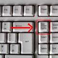 How to take a screenshot on different devices
 Wrong MMI code or wrong connection - problem solution
 Internet Explorer update